
Bidirectional shift register and display device incorporating same

a display device and register technology, applied in the field of bidirectional shift registers, can solve the problems of increasing the price of flexible wiring boards, albeit small, and reducing the competitiveness of cost, so as to reduce the manufacturing cost and reduce the manufacturing cos

Inactive Publication Date: 2006-02-07
SHARP KK
View PDF9 Cites 12 Cited by
  • Summary
  • Abstract
  • Description
  • Claims
  • Application Information

AI Technical Summary

Benefits of technology

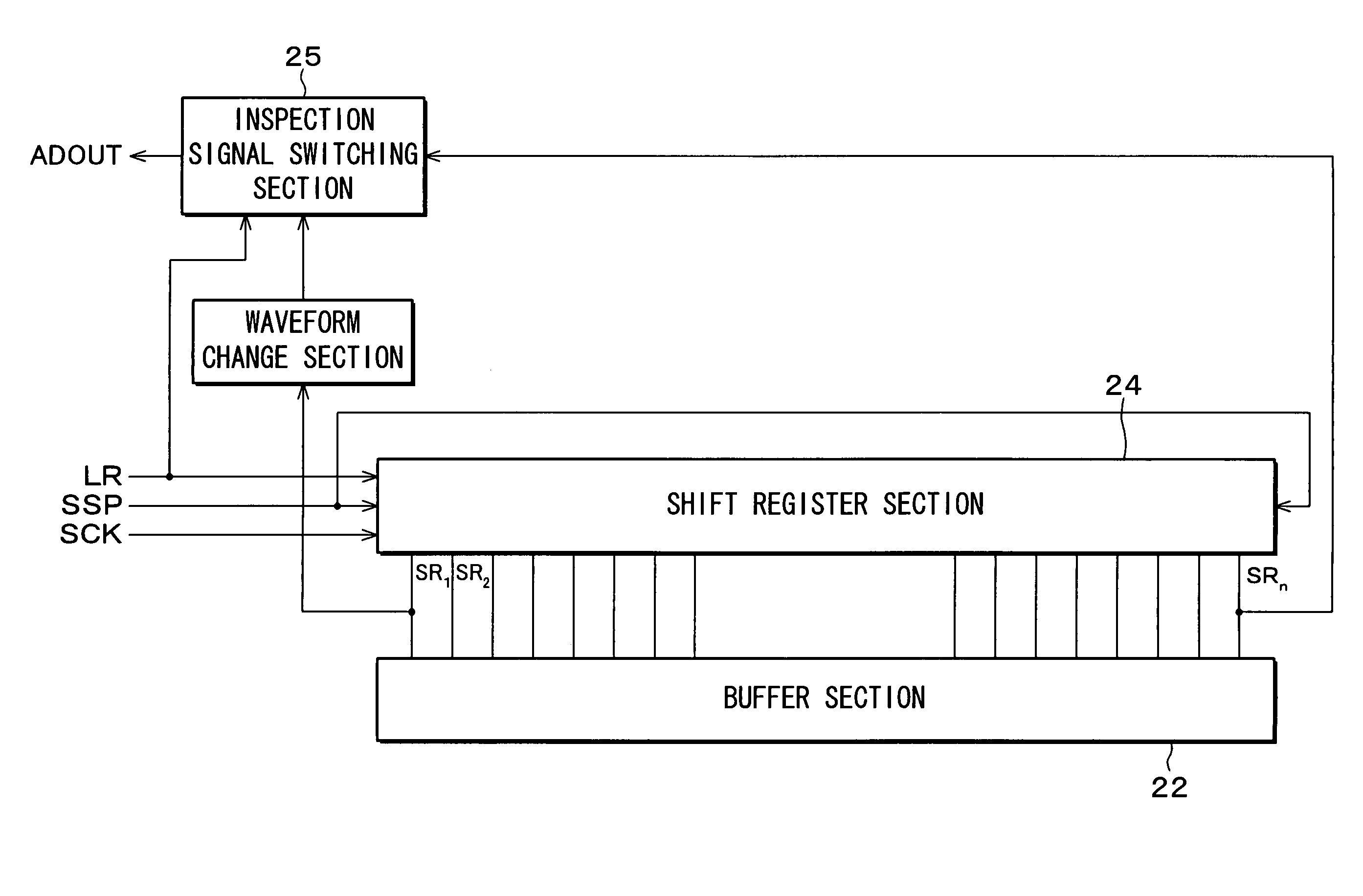
The present invention provides a bidirectional shift register and a display device incorporating the shift register. The shift register includes multiple-stage flip-flops operating in synchronism with a clock signal and a direction instruct signal. The shift direction can be switched based on the direction instruct signal. The shift register includes a waveform change section for changing the signal output in waveform, and an inspection signal switching section for switching the output between the waveform-changed signal and a signal output from the flip-flops in a different predetermined stage. The inspection signal switching section checks whether the shift register is operating correctly. The invention allows for checking the operation of the bidirectional shift register without fabricating the display device element on the same board and checking display state, reducing manufacturing costs. The display device includes pixels arranged in matrix, data signal lines, scan signal lines, and drive circuits for sequentially supplying a scan signal and a data signal to the pixels.

Problems solved by technology

These factors can amount to an increase, albeit small, in the price of the flexible wiring board.
If the inspection terminals are reduced in size, it takes a significantly long time to position the signal detection probes, which makes the approach less competitive in terms of cost.
However, although the bidirectional shift register 61 has received an instruction to change the state of the horizontal instruction signal LR, if the horizontal instruction signal LR is fixed in LOW state due to, for example, a defect of internal circuitry of the bidirectional shift register 61, following problems result among others.
The liquid crystal step is wasted, making it difficult to lower the manufacturing cost of the display device 51.

Method used


Image

  • Bidirectional shift register and display device incorporating same
  • Bidirectional shift register and display device incorporating same
  • Bidirectional shift register and display device incorporating same

Examples


Embodiment Construction

[0128]The following will describe embodiments of the present invention in reference to FIG. 1 through FIG. 15 and FIG. 29 through FIG. 40.

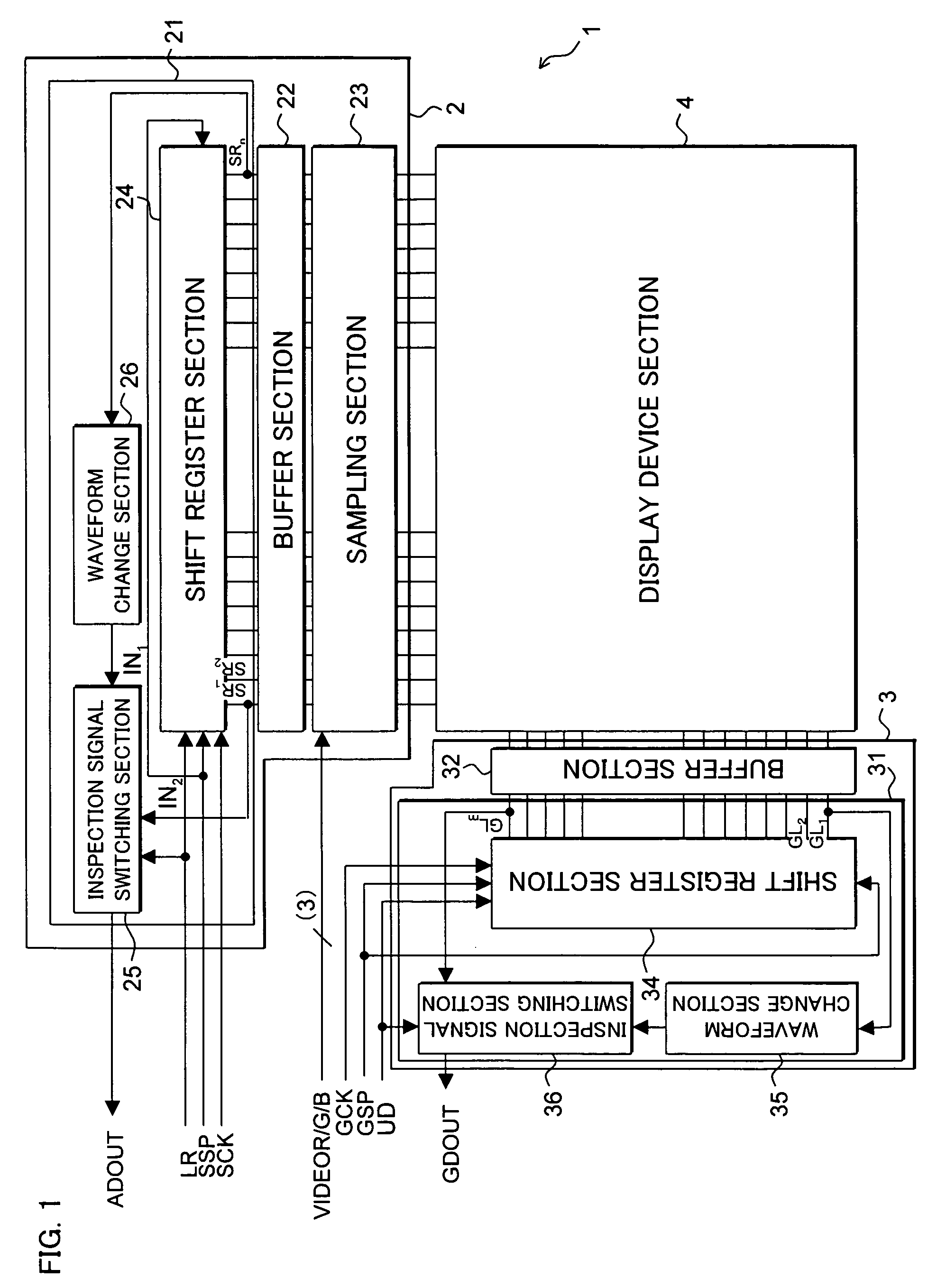
[0129]FIG. 1 is a block diagram showing a display device incorporating bidirectional shift registers in accordance with the present embodiment.

[0130]A display device 1 includes a data signal line drive circuit 2, a scan signal line drive circuit 3, and a display device section 4. The display device section 4 is identical to, the display device section 54 described in the BACKGROUND OF THE INVENTION section, and its description is therefore omitted here.

[0131]The data signal line drive circuit 2 includes a bidirectional shift register 21, a buffer section 22, and a sampling section 23. The buffer section 22 and the sampling section 23 are identical respectively to the buffer section 62 and the sampling section 63 described in the BACKGROUND OF THE INVENTION section, and their description is therefore omitted here.

[0132]The bidirectional shift regis...


PUM


Abstract

The present invention includes: a shift register section, including multiple-stage flip-flops operating in synchronism with a clock signal, for switching a shift direction in accordance with an externally supplied direction instruct signal; a waveform change section for changing in waveform a signal output of one of the flip-flops which is in a first predetermined stage; and an inspection signal switching section for switching, in accordance with the direction instruct signal, an output between the signal output which has been changed in waveform in the waveform change section and a signal output of one of the flip-flops which is in a second predetermined stage.

Description

[0001]This Nonprovisional application claims priority under 35 U.S.C. § 119(a) on Patent Applications No. 2003-165531 filed in Japan on Jun. 10, 2003 and No. 2003-315813 filed in Japan on Sep. 8, 2003, the entire contents of which are hereby incorporated by reference.FIELD OF THE INVENTION[0002]The present invention relates to bidirectional shift registers capable of switching the shift direction between two directions, as well as display devices incorporating such bidirectional shift registers.BACKGROUND OF THE INVENTION[0003]Bidirectional shift registers capable of producing bidirectional shift pulse outputs are conventionally known. Also known are those which are arranged to produce inspection signal outputs to inspect the operation of a bidirectional shift register.[0004]FIG. 16 is a block diagram showing a display device incorporating a bidirectional shift register arranged to produce inspection signal outputs. A display device 51, as shown in FIG. 16, includes a data signal li...

Claims


Application Information

Patent Timeline
Patent Type & Authority Patents(United States)
IPC IPC(8): G11C19/00G06F5/01G06F17/00G09F9/00G09G3/00G09G3/20G09G3/36G11C8/04G11C19/28G11C19/34H03K23/44
CPCG06F5/01G09G3/006G09G3/20G09G2330/12G09G2310/0275G09G2310/0283G09G2310/0289G09G2310/0267G11C19/28H03K23/44G09G3/36
Inventor ONDA, MAMORUWASHIO, HAJIMEHAYASHI, SHUNSUKEMUROFUSHI, HIROSHISUZUKI, NOBUHIKO
Owner SHARP KK
Learn More