
Method of noncontact dispensing of viscous material

a technology of viscous material and droplet, which is applied in the direction of superimposed coating process, liquid/solution decomposition chemical coating, manufacturing tools, etc., can solve the problems of corrosion and excessive thermal stress, too much epoxy can flow beyond the underside of the chip, interfere with other semiconductor devices and interconnections, etc., to reduce the size of the substrate, reduce the wetted area, and improve the effect of use efficiency

Inactive Publication Date: 2005-05-05
NORDSON CORP
View PDF23 Cites 24 Cited by
  • Summary
  • Abstract
  • Description
  • Claims
  • Application Information

AI Technical Summary

Benefits of technology

[0005] The present invention provides methods of noncontact jetting of a viscous material that reduce a wetted area on a substrate. The methods of the present invention make more efficient use of the dispensed material, which permits more efficient use of the substrate or a reduction in size of the substrate. In addition, by reducing wetted areas, the methods of the present invention provide a potential for greater dispenser velocities, which can reduce dispensing cycle times. Hence, the methods of the present invention are especially useful in performing an underfill operation and can potentially reduce production costs as well as product costs.
[0007] According to the principles of the present invention and in accordance with the described embodiments, the invention provides a method for noncontact dispensing a viscous material onto a surface of a substrate. The method first provides a jetting valve having a nozzle directing the viscous material flow in a jetting direction nonperpendicular to the surface of the substrate. The jetting process consists of causing the jetting valve to propel a flow of the viscous material through the nozzle with a forward momentum in the jetting direction, breaking the flow of the viscous material using the forward momentum to form a droplet of the viscous material, and applying the droplet of the viscous material to the surface of the substrate using the forward momentum of the droplet. The nonperpendicular jetting direction results in the droplet producing a reduced wetted area on the substrate.

Problems solved by technology

First, the wetted area represents epoxy that is not being used and is wasted.
Second, adjacent devices must be located on the PC such that they are outside the wetted area.
Too little epoxy can result in corrosion and excessive thermal stresses.
Too much epoxy can flow beyond the underside of the chip and interfere with other semiconductor devices and interconnections.

Method used


Image

  • Method of noncontact dispensing of viscous material
  • Method of noncontact dispensing of viscous material
  • Method of noncontact dispensing of viscous material

Examples


Embodiment Construction

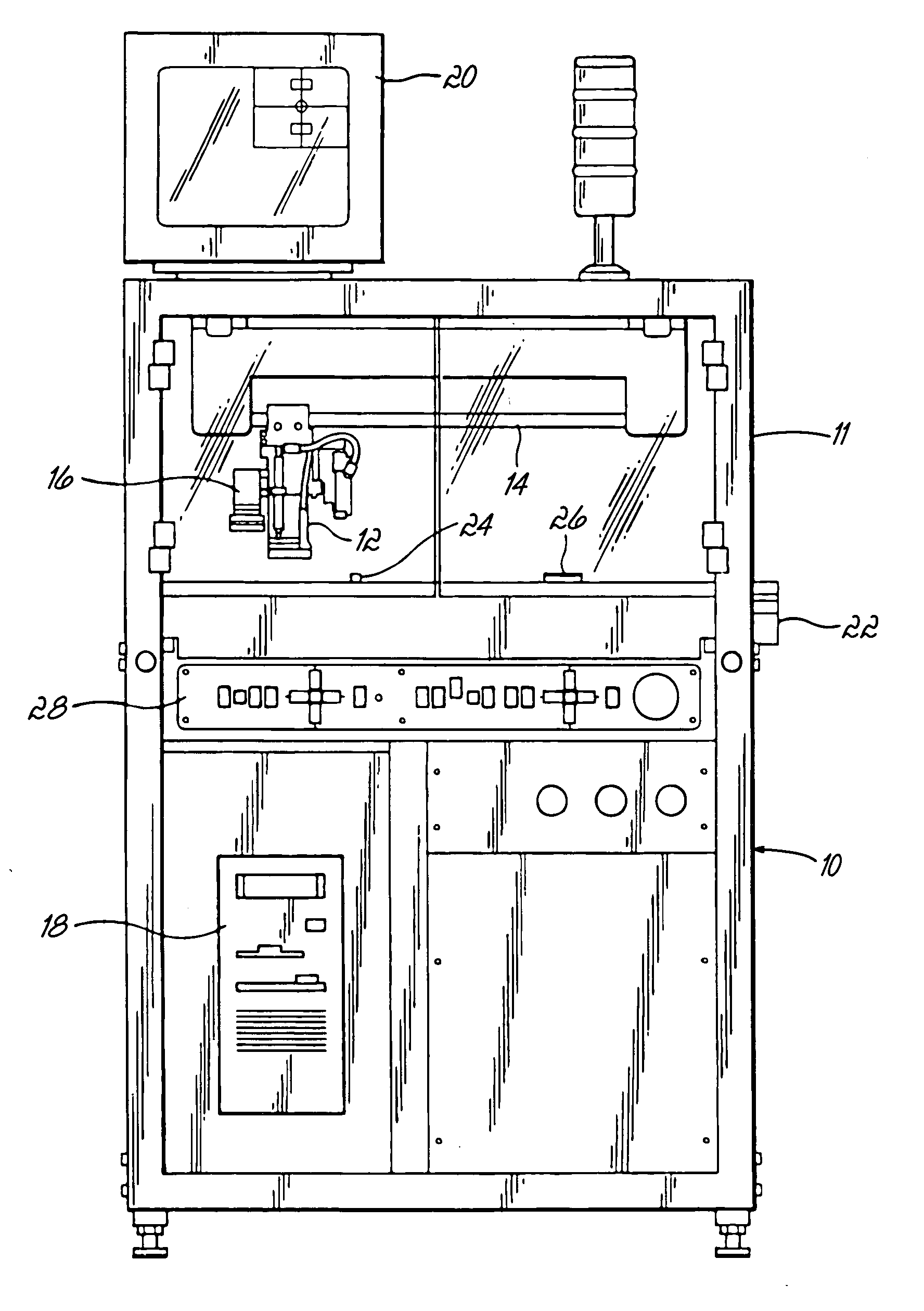
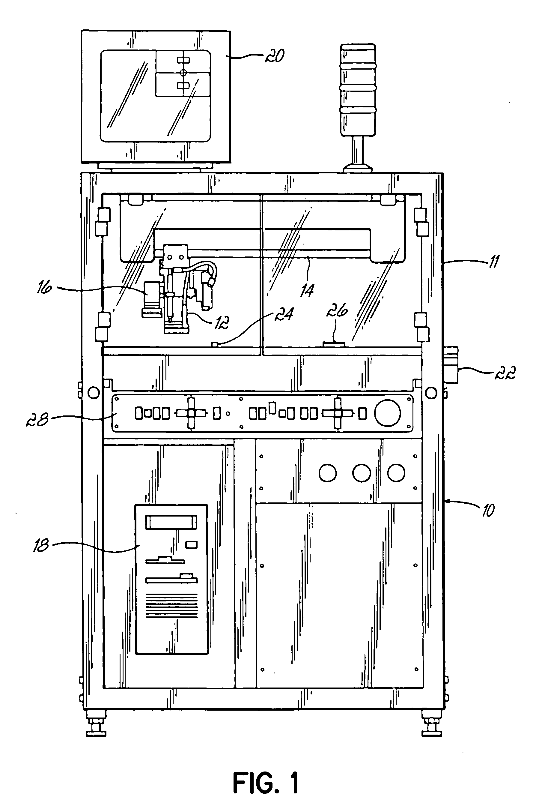
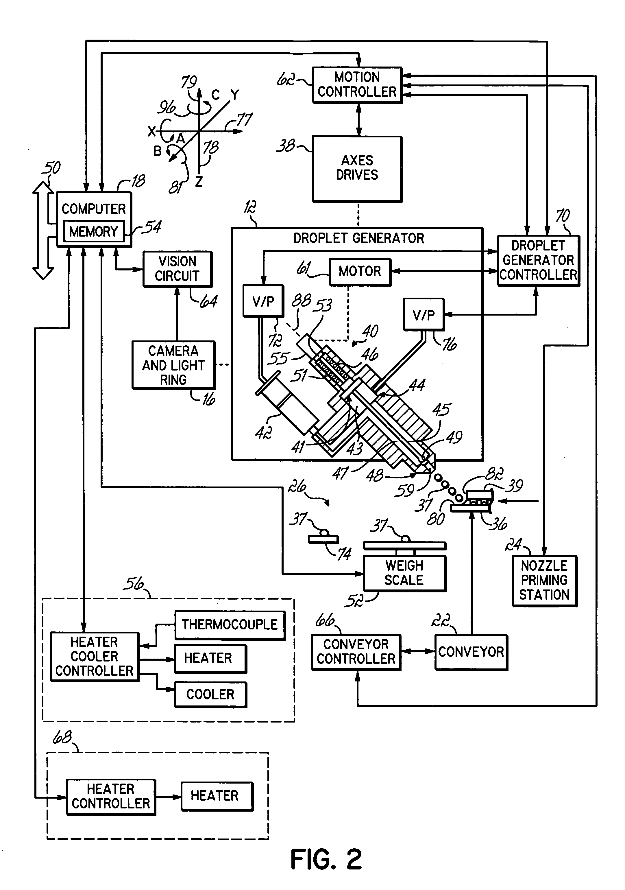
[0021]FIG. 1 is a schematic representation of a computer controlled noncontact viscous material jetting system 10, for example, an “AXIOM” X-1020 series commercially available from Asymtek of Carlsbad, Calif. A droplet generator 12 is mounted on a Z axis drive that is suspended from an X, Y positioner 14 in a known manner. The X, Y position 14 is mounted on a frame 11 and defines first and second nonparallel axes of motion. The X, Y positioner includes a cable drive coupled to a pair of independently controllable stepper motors (not shown) in a known manner. A video camera and LED light ring assembly 16 are connected to the droplet generator 12 for motion along the X, Y and Z axes to inspect dots and locate reference fiducial points. The video camera and light ring assembly 16 may be of the type described in U.S. Pat. No. 5,052,338 entitled “APPARATUS FOR DISPENSING VISCOUS MATERIALS A CONSTANT HEIGHT ABOVE A WORKPIECE SURFACE”, the entire disclosure of which is incorporated be refe...


PUM

PropertyMeasurementUnit
viscosityaaaaaaaaaa
angleaaaaaaaaaa
angleaaaaaaaaaa

Abstract

A method of noncontact dispensing a viscous material onto a surface of a substrate, which uses a jetting valve having a nozzle directing the viscous material flow in a jetting direction nonperpendicular to the surface of the substrate. The nonperpendicular jetting direction results in the droplet producing a reduced wetted area on the substrate.

Description

FIELD OF THE INVENTION [0001] The present invention generally relates to the dispensing of viscous materials and more particularly, to a method of noncontact dispensing of droplets of viscous materials. BACKGROUND OF THE INVENTION [0002] In the manufacture of substrates, for example, printed circuit (“PC”) boards, it is frequently necessary to apply small amounts of viscous materials, i.e. those with a viscosity greater than fifty centipoise. Such materials include, by way of example and not by limitation, general purpose adhesives, solder paste, solder flux, solder mask, grease, oil, encapsulants, potting compounds, epoxies, die attach pastes, silicones, RTV and cyanoacrylates. [0003] In the quest for ever increasing miniaturization of circuitry, a fabrication process known as flip chip technology has developed, which has multiple processes that require viscous fluid dispensing. For example, as shown in FIG. 8, a device 39, for example, a semiconductor die or chip, is attached to a...

Claims


Application Information

Patent Timeline
Patent Type & Authority Applications(United States)
IPC IPC(8): B05D1/02B05D1/26B05D3/04B05D5/12H01L21/00H01L21/56
CPCB05D3/042H01L21/563H01L21/6715H01L2924/0002H01L2924/00H01L2224/75611H01L2224/75822H01L2224/75824H01L24/75B05D1/02
Inventor BABIARZ, ALEC J.FANG, LIANGFISKE, ERIKLEWIS, ALAN RAYQUINONES, HORATIOSNOWDEN, GREGGORY EUGENEWILDE, TERRY P. JR.
Owner NORDSON CORP
Learn More