
Direct access arrangement

a direct access and arrangement technology, applied in the field of communication systems, can solve the problems of large or discrete parts used in daa implementations that address current feedback, distortion and noise, and conflicting needs, and achieve the effects of reducing the number of discrete parts, and reducing the number of direct access arrangements

Inactive Publication Date: 2005-05-05
MITEL
View PDF17 Cites 5 Cited by
  • Summary
  • Abstract
  • Description
  • Claims
  • Application Information

AI Technical Summary

Benefits of technology

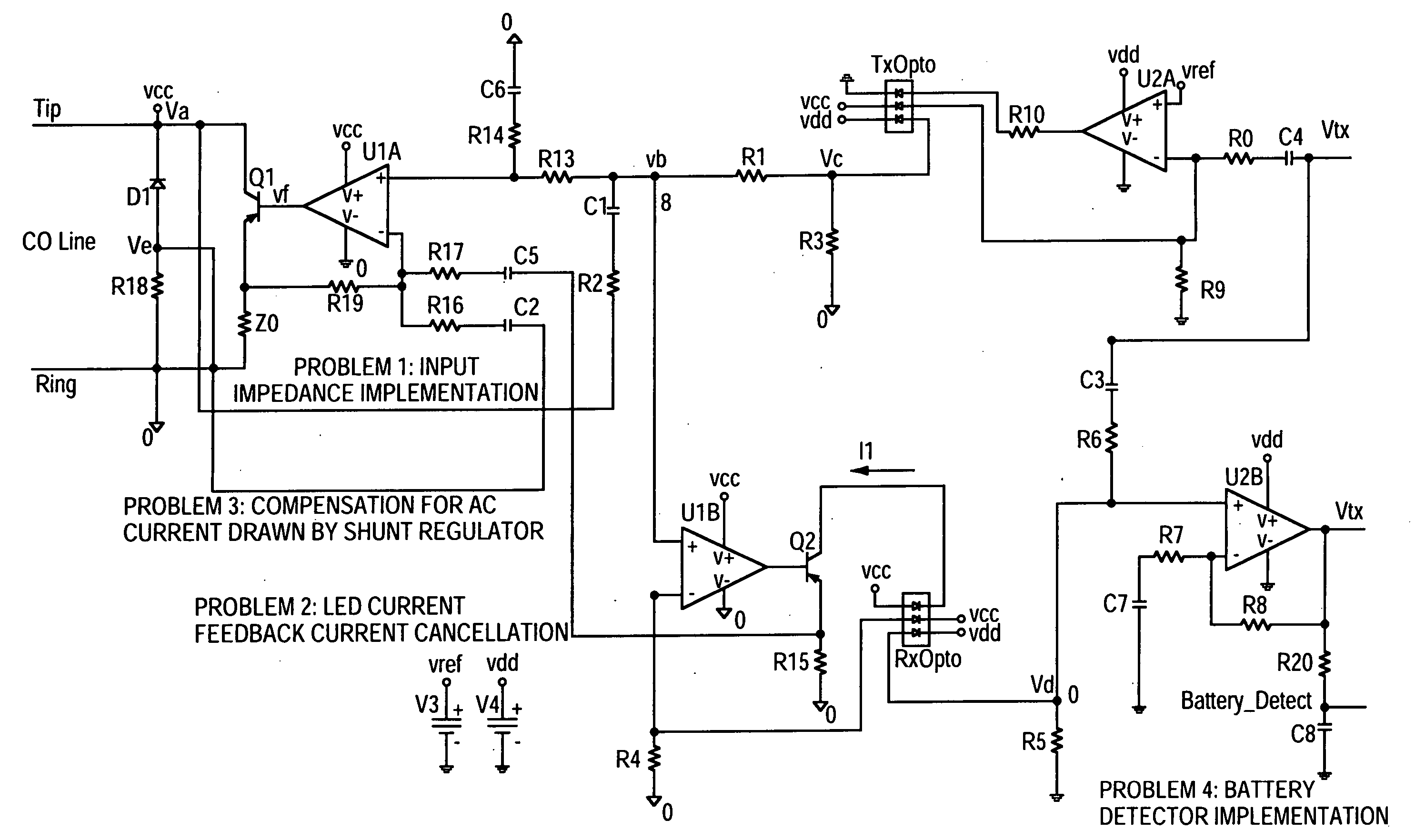
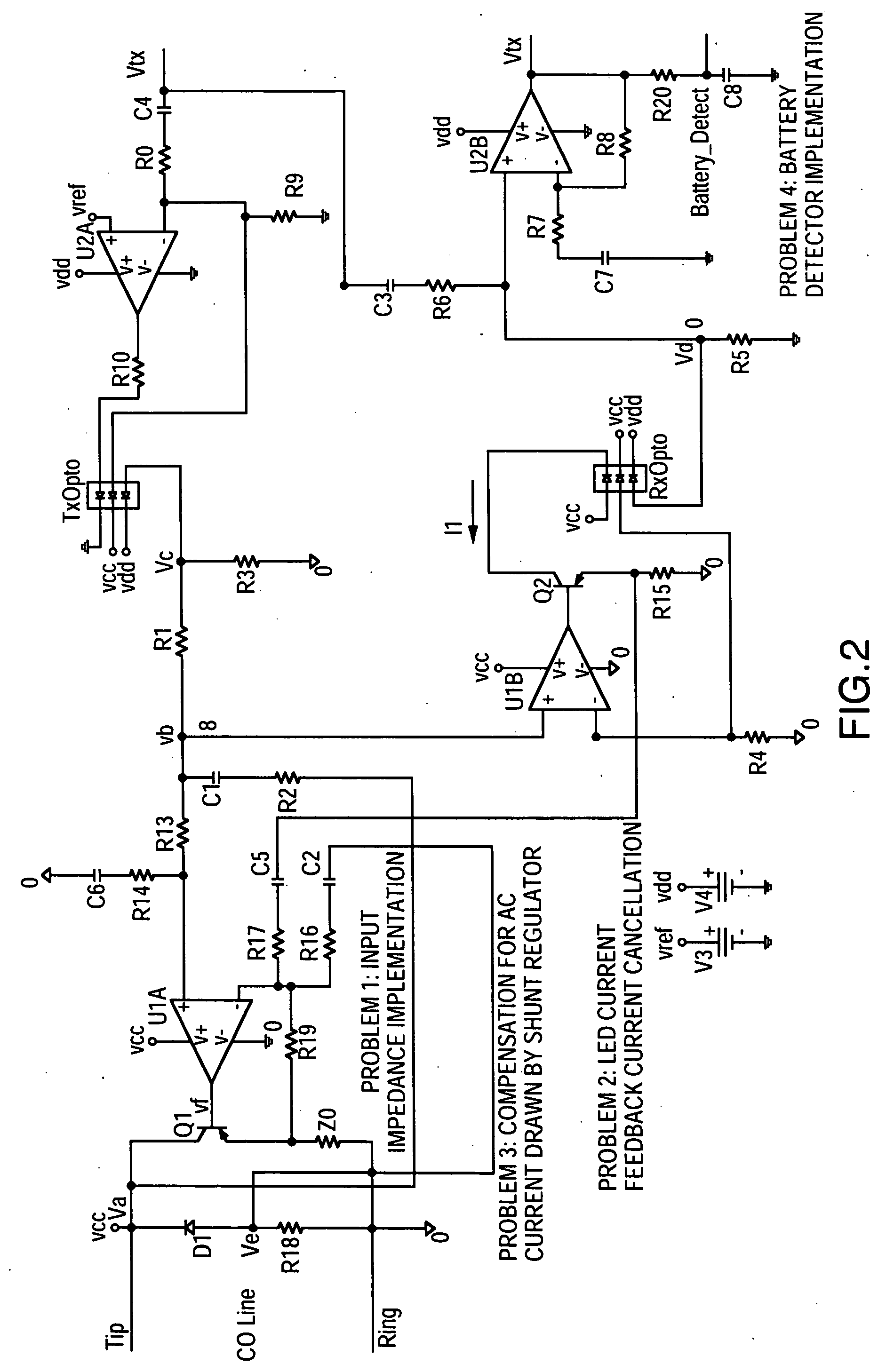
The invention relates to a device called a DAA that acts like a current source to generate an AC current in the tip and ring of an optical fiber based on the voltage on the device. This device also monitors the feedback AC current and generates an equal and opposite current to cancel out the feedback. Additionally, the invention includes a shunt regulator that draws or sinks DC current from the optical fiber. The device also senses the DC bias current and provides a battery detect function, eliminating the need for a separate isolated battery detector. These technical effects improve the performance and functionality of optical fiber devices.

Problems solved by technology

However, the use of discrete components conflicts with the need for compact placement discussed above.
Filtering tip and ring for power usage introduces extra bulky components while directly coupling the tip and ring to the line side circuitry introduces AC current feedback signals that cause distortion and noise.
The above-discussed prior art DAA implementations that address current feedback suffer from extensive use of large or discrete parts.
This is also in conflict with the aforementioned goal of compact placement.
Such gyrators use large reactive components, or alternatively, introduce high distortion and add to cost and real estate.
Finally, with reference to the DAA requirement of providing line status detection, the prior art teaches the use of battery detector circuits implemented by inserting an isolated current or voltage sensor in the current path, thereby adding to cost and real estate.

Method used


Image

  • Direct access arrangement
  • Direct access arrangement
  • Direct access arrangement

Examples


Embodiment Construction

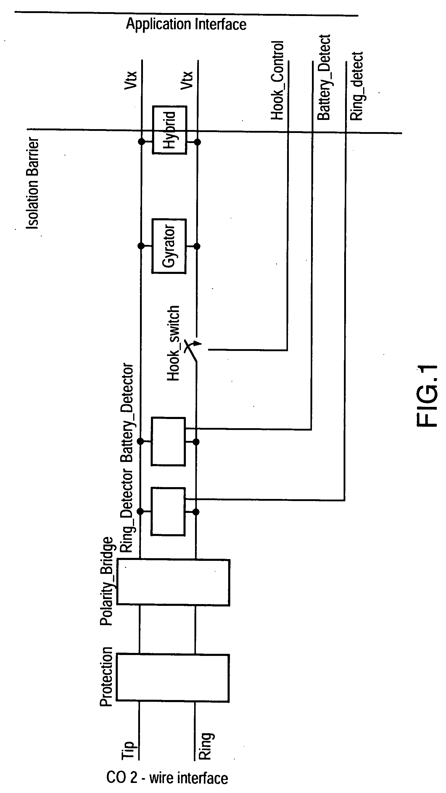
[0019] Turning to FIG. 1, a prior art DAA is shown connected to the CO line.

[0020] The two-wire CO line includes a tip and ring pair that is connected to an over-voltage protection circuit which, in turn, is connected to a polarity circuit (e.g. diode bridge) to define proper line polarity for the DAA circuitry. The purpose of the protection circuit is to prevent over-voltages from damaging the DAA or device.

[0021] A ring detector and a battery detector are connected in parallel to detect ringing voltage on the CO line and line availability, respectively. A hook switch controls on / off hook status of the DAA. A gyrator is connected to the line pair via the hook switch for sinking 20-120 mA DC current, for POTS compatibility.

[0022] A hybrid provides two-to-four-wire signal conversion between the bi-directional line pair and unidirectional transmit (Vtx) and receive (Vrx) lines. Additional circuitry provides the necessary input impedance.

[0023] The line side signals must be isolate...


PUM


Abstract

The present invention is directed towards a low cost Data Access Arrangement (DAA) with improved current control for controlling the current drawn from a telephone line pair to drive the light emitting diodes (LEDs) in an opto-isolator utilized with the DAA, and to an enhanced method of sinking DC line current. Also, an improved method is provided to implement line current draw and battery detect features.

Description

FIELD OF THE INVENTION [0001] This invention relates in general to communication systems, and more particularly to a Direct Access Arrangement (DAA) incorporating optocouplers for interfacing analog devices (e.g. telephone, modem, fax) to a Central Office (CO) or Private Branch Exchange (PBX). BACKGROUND OF THE INVENTION [0002] DAAs provide an interface between the CO telephone line (tip and ring pair) and analog devices such as a telephone, modem, or fax machine. A DAA is required to perform several functions in accordance with the national specifications of a country. The tip and ring pair is required to be compatible with Plain Old Telephone Service (POTS), giving rise to the requirement that the DAA, for the purposes of coupling with the CO line, must resemble a POTS device. [0003] In order to resemble a POTS device, the DAA must perform a number of electrical functions. It must provide over-voltage protection from signaling or environmental conditions such as lightning, power c...

Claims


Application Information

Patent Timeline
Patent Type & Authority Applications(United States)
IPC IPC(8): H04B1/58H04M11/06
CPCH04M11/06
Inventor AHMED, TAHIR
Owner MITEL
Learn More