
Optical pickup including polarization holographic optical element and photodetector

a holographic optical element and optical pickup technology, applied in the field of optical pickups, can solve the problems of adversely affecting the ability of optical pickups, difficult control of pickups, and lower optical efficiency, and achieve the effect of simple polarization

Inactive Publication Date: 2005-05-05
SAMSUNG ELECTRONICS CO LTD
View PDF6 Cites 2 Cited by
  • Summary
  • Abstract
  • Description
  • Claims
  • Application Information

AI Technical Summary

Benefits of technology

[0010] The present invention provides an optical pickup that comprises a simple polarization holographic optical element (HOE) and a photodetector used to record and / or reproduce information to and / or from an optical disc.

Problems solved by technology

In conventional photodetectors and HOEs with complicated configurations and patterns, it is difficult to control a pickup and lower optical efficiency results from the splitting of light.
The heat can adversely affect the ability of an optical pickup in sultry weather.
In particular, the optical length of an optical system changes and optical components suffer deviations from their normal positions under high temperature conditions.
Since optical elements in an optical pickup are bonded using an ultraviolet (UV) curing adhesive, the bonded portions suffer misalignment or expansion at high temperatures, which causes a beam transmitted or reflected by the optical elements to deviate from its intended path or a focal point of the optical beam to become out of focus.
This may degrade jitter characteristics.

Method used


Image

  • Optical pickup including polarization holographic optical element and photodetector
  • Optical pickup including polarization holographic optical element and photodetector
  • Optical pickup including polarization holographic optical element and photodetector

Examples


Embodiment Construction

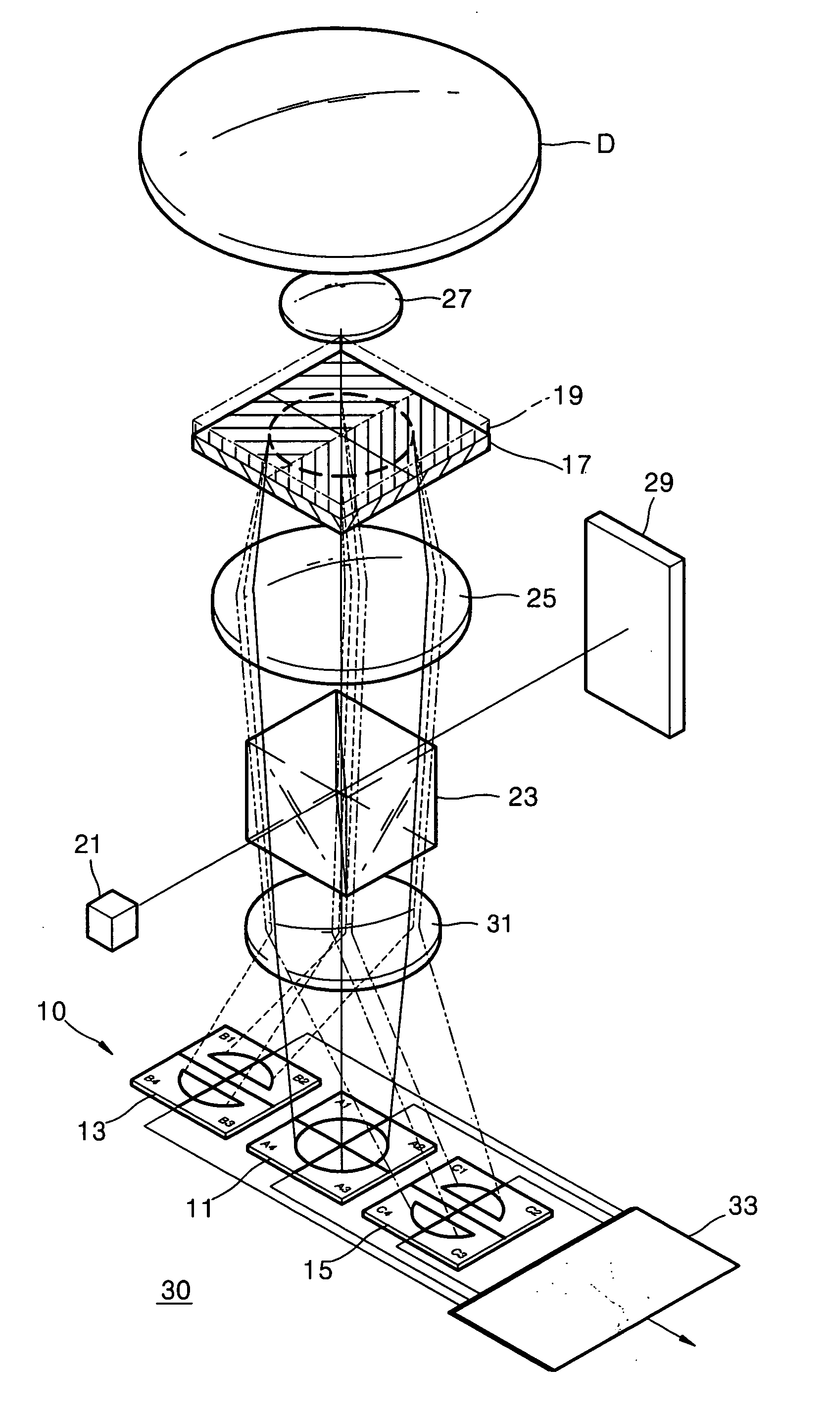
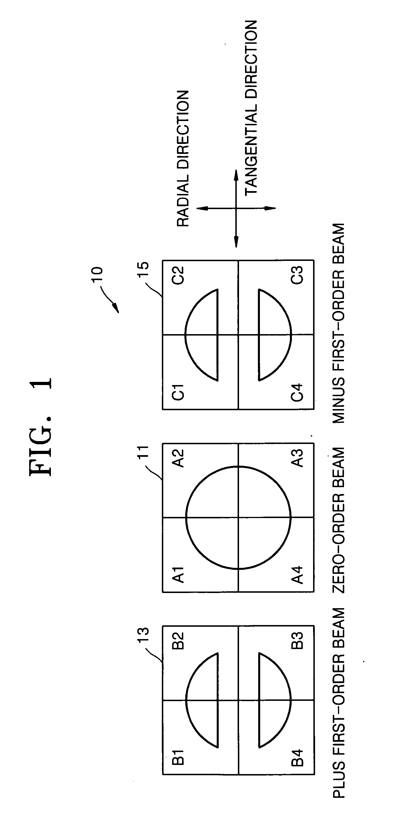
[0023] Referring to FIG. 1, a photodetector 10 according to an embodiment of the present invention includes a first light-receiving portion 11 divided into four (2 by 2) quadrants A1 through A4, a second light-receiving portion 13 divided into four (2 by 2) quadrants B1 through B4, and a third light-receiving portion 15 divided into four (2 by 2) quadrants C1 through C4. The second and third light-receiving portions 13 and 15 are symmetrically disposed on either side of the first light-receiving portion 11 in a tangential direction. The first through third light receiving portions 11, 13, and 15 receive zero-order, plus first-order, and minus first-order beams, respectively. While the zero-order beam is circular, each of the plus and minus first-order beams is separated into two parts in the radial direction. That is, the plus first-order beam is separated and focused onto the upper two quadrants B1 and B2 and the lower two quadrants B3 and B4 of the second light-receiving portion 1...


PUM

PropertyMeasurementUnit
temperatureaaaaaaaaaa
wavelengthaaaaaaaaaa
optical efficiencyaaaaaaaaaa

Abstract

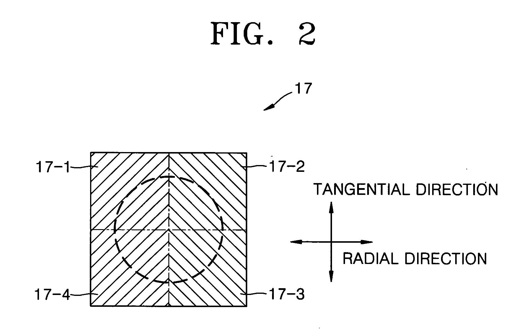
Disclosed is an optical pickup including a polarization holographic optical element (HOE) and a photodetector. The optical pickup includes a light source, an optical path changer, an objective lens, a polarization HOE, and a photodetector. The polarization HOE has a pattern designed to generate different astigmatisms in the left and right halves of the polarization HOE in a tangential direction and to divide plus and minus first-order beams in a radial direction. The photodetector includes a first light-receiving portion receiving a zero-order beam and second and third light-receiving portion that are disposed on either side of the first light-receiving portion in the tangential direction and respectively receive the plus and minus first-order beams.

Description

CROSS-REFERENCE TO RELATED APPLICATION [0001] The present application is related to Korean Patent Application No. 2003-35298, filed on Jun. 2, 2003 in the Korean Intellectual Property Office, the entire contents of which are incorporated herein by reference. BACKGROUND OF THE INVENTION [0002] 1. Field of the Invention [0003] The present invention relates to an optical pickup including a polarization holographic optical element (HOE) and a photodetector. More particularly, the present invention relates to an optical pickup including a polarization HOE designed to effectively split light and a photodetector with a reduced number of sections to receive light transmitted through the polarization HOE. [0004] 2. Description of the Related Art [0005] In conventional photodetectors and HOEs with complicated configurations and patterns, it is difficult to control a pickup and lower optical efficiency results from the splitting of light. A conventional optical pickup is disclosed in Korean Pa...

Claims


Application Information

Patent Timeline
Patent Type & Authority Applications(United States)
IPC IPC(8): G11B7/095G11B7/135
CPCG11B7/1353G11B7/0956
Inventor KIM, BONG-GIPARK, SOO-HANPAE, JUNG-GUGHEOR, TAE-YOUN
Owner SAMSUNG ELECTRONICS CO LTD
Learn More