
Method and device for changing over a first mode of a control device to a second mode, via a data bus

Inactive Publication Date: 2005-05-05
ROBERT BOSCH GMBH
View PDF12 Cites 15 Cited by
  • Summary
  • Abstract
  • Description
  • Claims
  • Application Information

AI Technical Summary

Benefits of technology

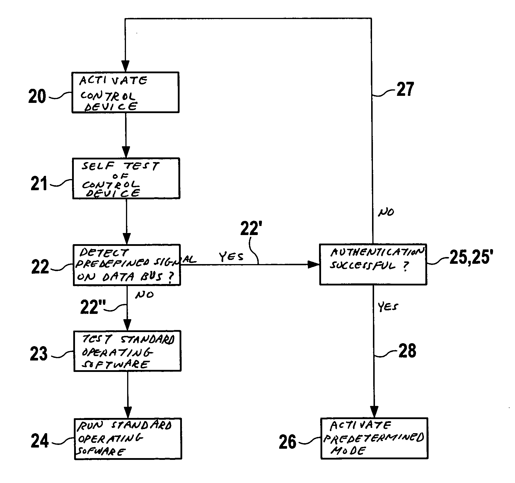
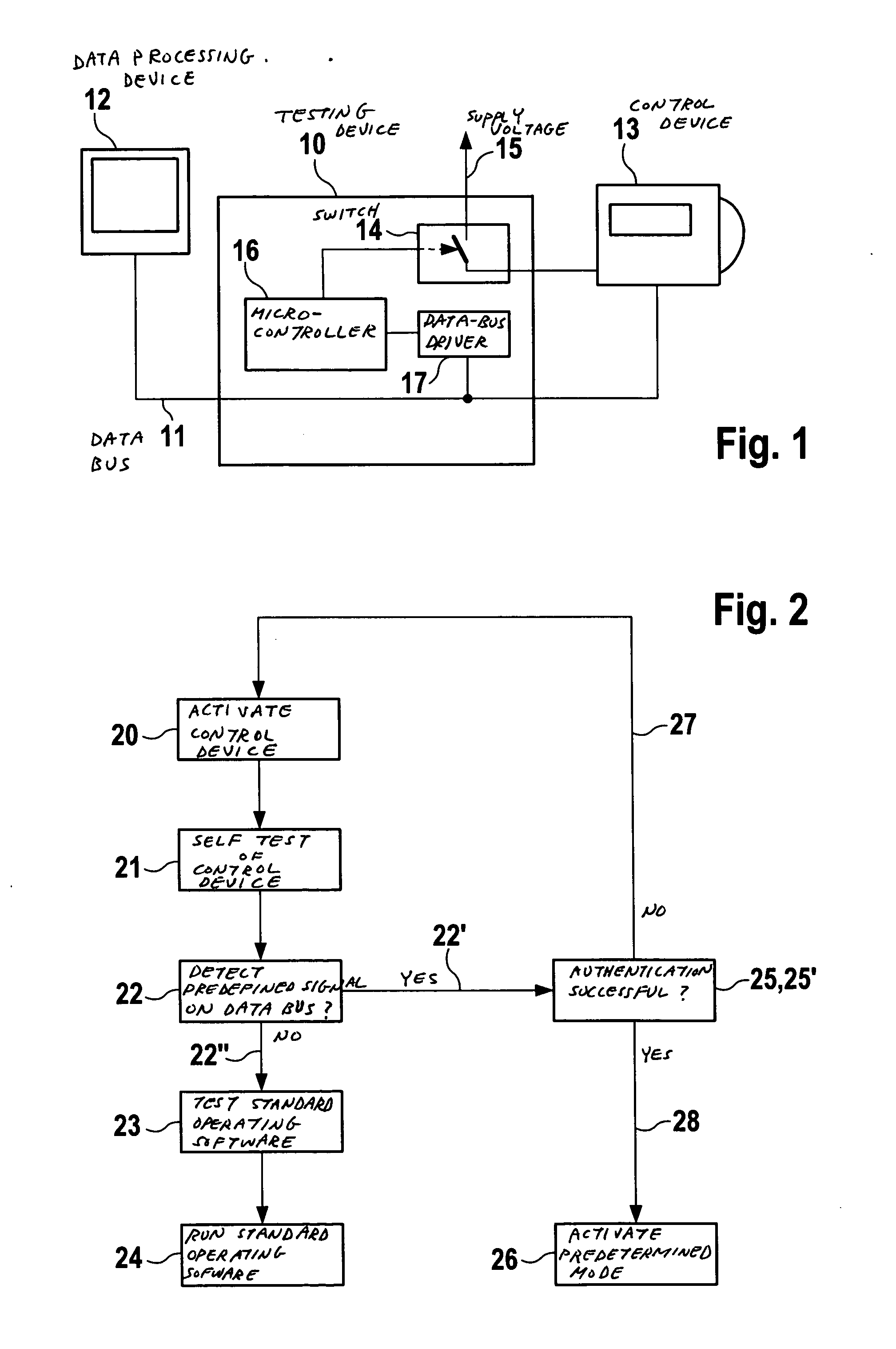
[0005] An example embodiment of the present invention for changing over a mode of a control device via a data bus has the advantage over the known art that, apart from the data-bus communication connection, no additional control-unit pins are necessary to implement the change over, and that a reliable entry condition for a test mode may be generated in a cost-effective manner. Due to the predefined characteristics of the entry condition, a very high level of protection is provided against an accidentally occurring entry condition for the test mode. As protection against misuse, there is also the option of using an authentication method, such as the seed & key method, in order to authorize a tester or test device of the manufacturer to test and / or program the control unit. Therefore, a two-stage safety measure may be provided, which is based on both software algorithms and physical quantities.
[0009] According to another example embodiment of the present invention, the predetermined second mode is a test mode for checking and / or programming the control device, and the access security is provided after the changeover to the predetermined second mode, in order to be able to re-program preset parameters of the control device, which may be stored in a programmable memory, e.g., on an EEPROM. The advantage of this is that the control device is programmable after passage through a security measure, which protects against unauthorized access to predefined control-unit parameters.
[0010] According to another example embodiment of the present invention, the access security is provided using the seed & key authentication method. This method provides a high level of security for the authorization of access to core functions of the control unit.
[0013] According to another example embodiment of the present invention, a change-over to the predetermined second mode occurs when a predefined number of clock-pulse periods of the predefined signal, e.g., at least 16 clock-pulse periods or at least 32 clock-pulse periods, is measured. This measure provides additional security against unwanted or unintended change-over into the predetermined second mode.
[0014] According to another example embodiment of the present invention, the predefined signal for changing over the control device from the first mode to the second mode is supplied by a testing device to the data bus for a predefined period of time, until the predefined signal is detected by the control device, and the control device may be activated at the same time as the predefined signal is applied via a switching device. This provides an additional safety measure since the control device is able to receive the predefined signal only for the predefined period of time after the control device has been activated.

Problems solved by technology

Such special functions (or test functions) may not be executable during the future operation of the control units, since unwanted behavior of the control unit could otherwise be produced.
In a motor vehicle, this would produce, for example, an unacceptable safety risk during normal operation, e.g., when control units of safety-relevant components such as the drive system or the brake system would execute manufacturer test functions.
In the above-explained design approach, it is disadvantageous that, in addition to the communication lines such as CAN lines or K lines, additional connector pins such as sensor connections are necessary for applying the signals for providing the entry condition.
However, control units, which only have a supply-voltage connection and data-bus connection, do not provide any additional control-unit pins, via which signals may be applied to provide an entry condition to the control unit to be tested at the factory.

Method used


Image

  • Method and device for changing over a first mode of a control device to a second mode, via a data bus
  • Method and device for changing over a first mode of a control device to a second mode, via a data bus

Examples


Embodiment Construction

[0018]FIG. 1 shows a testing device 10, which is connected to a data-processing device 12, e.g., a PC, via a data bus 11. Testing device 10 is also connected to a control device 13, e.g., a motor-vehicle control unit, via data bus 11, the motor-vehicle control unit being able to be tested with the aid of testing device 10 and data-processing device 12. Testing device 10 has a switching device 14, e.g., a bipolar transistor, via which control device 13 may be connected to a supply voltage 15, for example 14.5 V. Switching device 14 is coupled to a further control device 16, e.g., a micro-controller. Micro-controller 16 is connected to a data-bus driver device 17, e.g., a CAN driver, which is coupled to data bus 11.

[0019] In order to reset the control device 13, e.g., a sensor control unit (SCU), from a first mode, e.g., a standard operating mode, to a predetermined second mode, e.g., a manufacturer test mode, an entry condition must be fulfilled. This entry condition is generated in...


PUM


Abstract

A method and a system for switching between a first operating mode and a second operating mode of a target control device connected to a data bus are provided. After activation of the target control device, a test device generates a predefined signal to be transmitted on the data bus, the predefined signal having a predefined frequency and a predefined pulse-duty factor. The target control device is switched from the first operating mode to the second operating mode in response to detecting the predefined signal transmitted on the data bus.

Description

FIELD OF THE INVENTION [0001] The present invention generally relates to a method and a device for changing over a mode of a control device, via a data bus, and particularly relates to a method and a device for changing between a standard operating mode and a factory test mode of a motor-vehicle control unit, via a CAN bus. BACKGROUND INFORMATION [0002] As either a part of the manufacturing process or after completion of the manufacturing process, motor-vehicle control units, which include micro-controllers, for example, must be tested for their functionality at the factory. To this end, special software functions, which are only used to test the control units at the factory and are no longer necessary during later operation by the actual user, must be provided in the control unit. Such special functions (or test functions) may not be executable during the future operation of the control units, since unwanted behavior of the control unit could otherwise be produced. In a motor vehic...

Claims


Application Information

Patent Timeline
IPC IPC(8): H04B1/00H04L12/40H04Q1/00
CPCH04L12/40006H04L2012/40273H04L2012/40215H04L12/4135
Inventor WACKERL, OLIVERJORDAN, RUEDIGER
Owner ROBERT BOSCH GMBH
Learn More