
Binderless preform manufacture

Inactive Publication Date: 2005-05-05
PURDUE RES FOUND INC +1
View PDF45 Cites 25 Cited by
  • Summary
  • Abstract
  • Description
  • Claims
  • Application Information

AI Technical Summary

Benefits of technology

[0014] This invention thus provides a means for moving a compacted preform directly to a resin / pitch infiltration or RTM process, without the need for a binder resin or a preliminary rigidifying step such as Carbon Vapor Deposition. The novel constraint fixture of the mold described in this invention holds the loose fill materials (fibers, fillers, additives) in the desired location without binder or the need to rigidify by CVD. Alternatively, one could insert woven or nonwoven fabric layers into the mold constraint apparatus of this invention. Once the preform is positioned within the constraint fixture, the loose fill material preforms (or even fabric preforms) can be densified by an infiltration process without the risk of delamination or other deterioration.

Problems solved by technology

As such, they require multiple and costly manufacturing steps to reach high density levels (>1.8 g / cc) for better heat capacity and system weight reduction.

Method used


Image

  • Binderless preform manufacture
  • Binderless preform manufacture
  • Binderless preform manufacture

Examples


Embodiment Construction

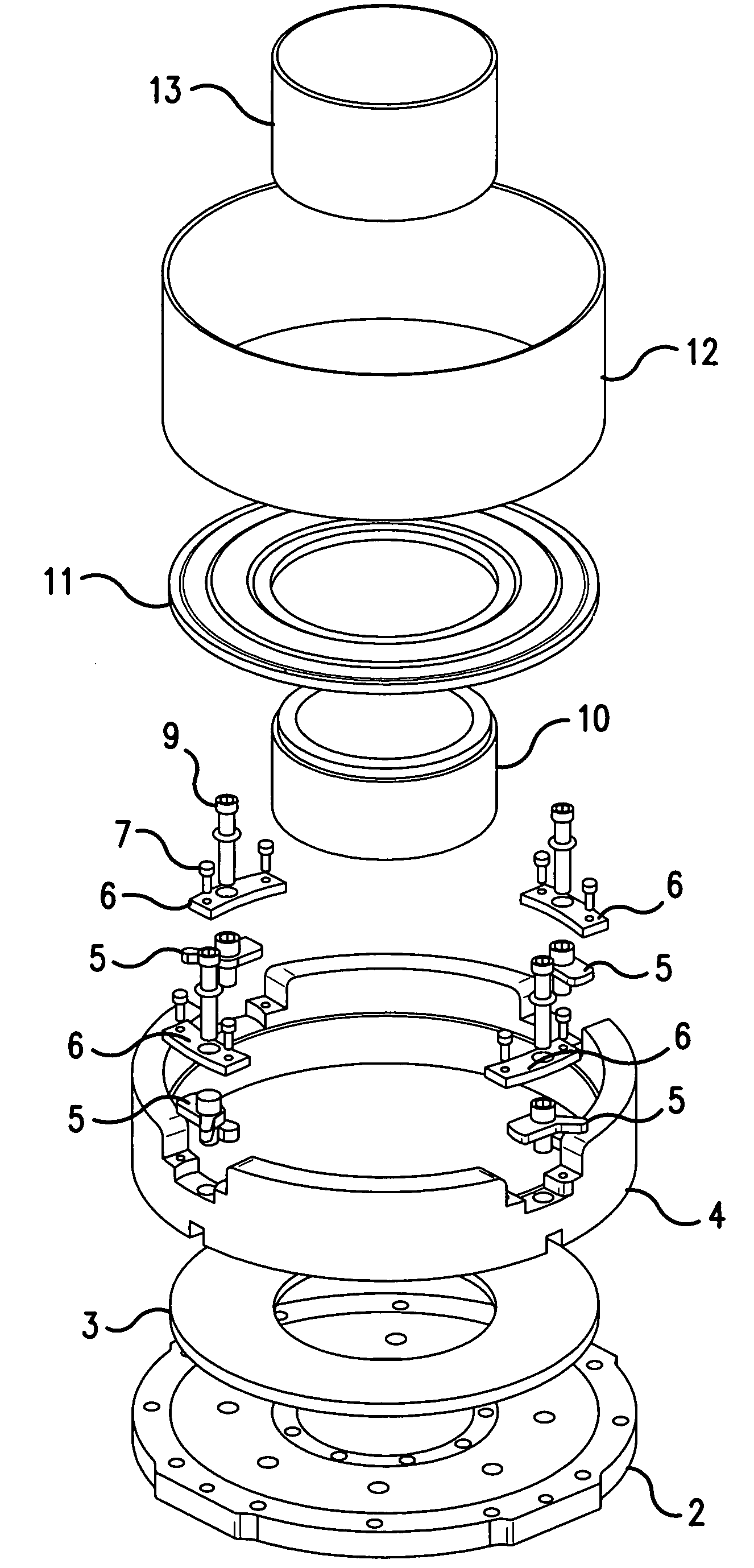
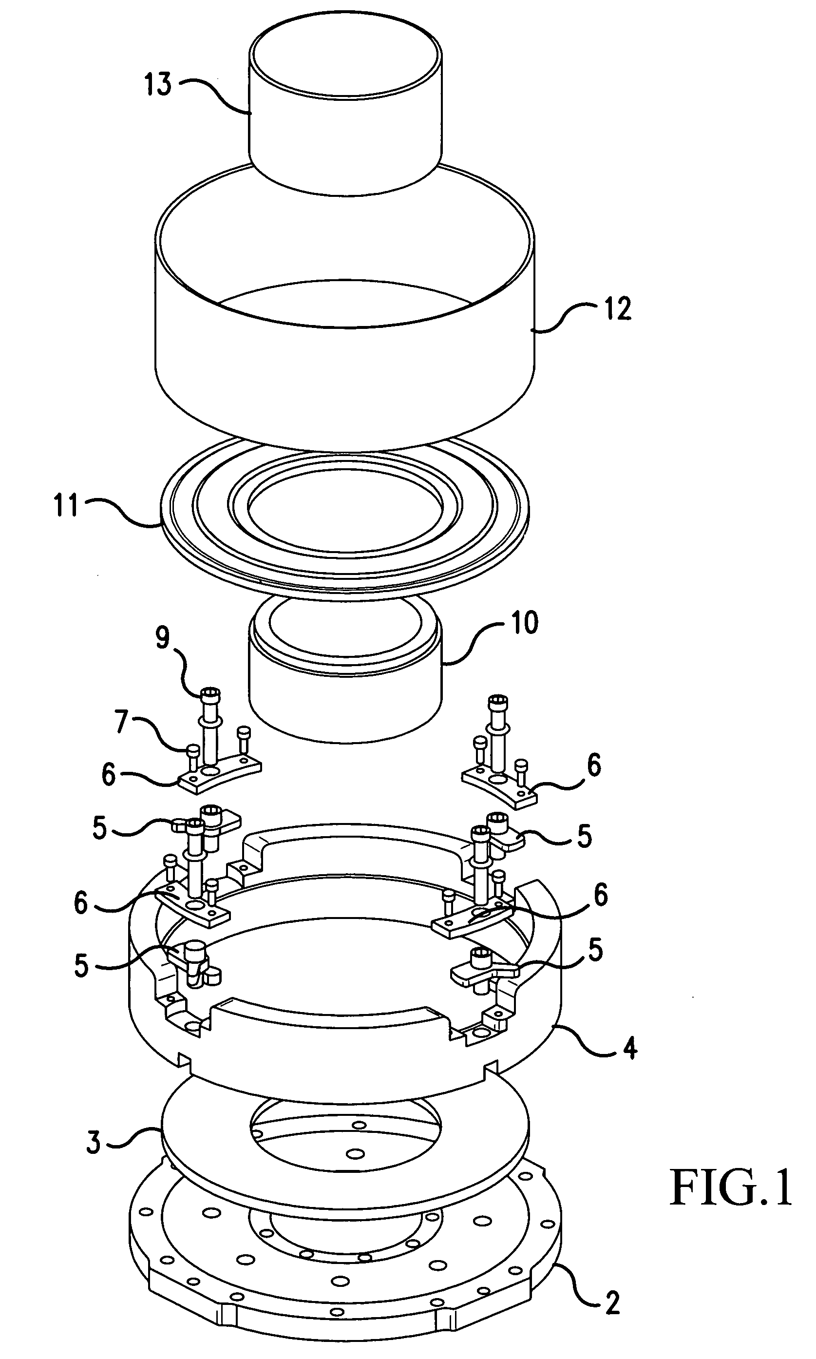
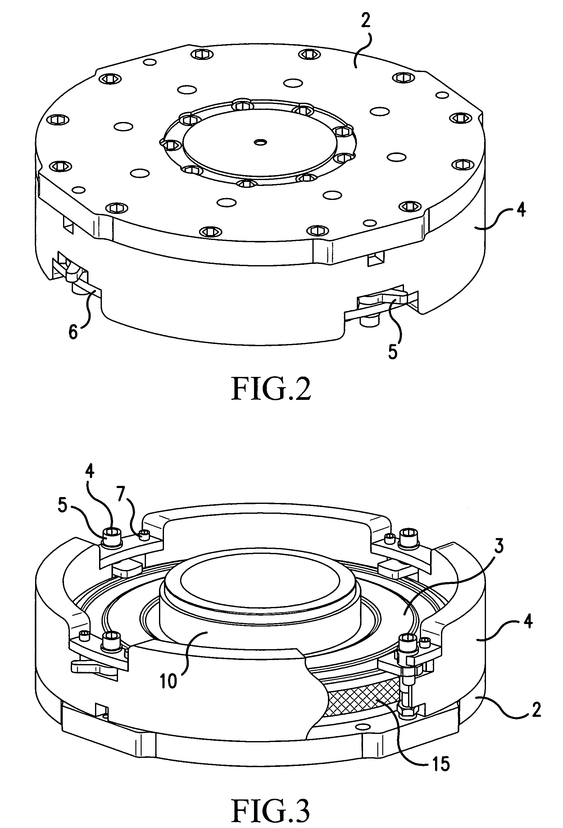
[0028] This invention provides a preform mold apparatus for brake friction components. The apparatus of the invention comprises a constraint fixture having a bottom plate (2) and an internal area corresponding in shape to the shape of a desired preform. That internal area is defined by an annular ejector plate (3, 3′), generally perforated, a inner wall (10), an outer wall (4), and an annular top plate (11, 11′), also generally perforated. The bottom plate (2) may advantageously comprises holes (21 ) to facilitated ejection of ejector plate (3,3′).

[0029] The apparatus may be used with annular inner and outer filling rings (13, 12) to facilitate loading of the mold with fibrous materials. Those rings serve to guide chopped fibers and any fillers or other additives into the internal area of the constraint fixture.

[0030] The apparatus of this invention may include locking means, e.g., a plurality of locking cams (5), to maintain the top plate in place in the constraint fixture once t...


PUM

PropertyMeasurementUnit
Pressureaaaaaaaaaa
Densityaaaaaaaaaa
Shapeaaaaaaaaaa

Abstract

The present invention makes use of loose fibrous material (for instance, chopped fibers) as reinforcement matrix material in the manufacture of carbon-carbon composites. In accordance with this invention, a constraint fixture is provided which can be separated from the mold. The constraint fixture has an internal shape corresponding to the shape of a desired preform component, with the internal shape being defined by a bottom plate (2), an annular ejector plate (3, 3′), a inner wall (10), an outer wall (4), and an annular top plate (11, 11′). The constraint fixture is normally made of metal, porous ceramic, or carbon material. The constraint fixture of the mold holds the loose matrix materials (fibers, along with any fillers and / or additives). The mold assembly itself is segmented, so that the constraint, fixture and the loose fill materials in the fixture can be removed and subjected to further processing as a unit. Such further processing may include Chemical Vapor Deposition or resin or pitch infiltration or Resin Transfer Molding. The preform matrix may remain in the constraint fixture through such processing steps as densification and until it is removed therefrom for final machining.

Description

[0001] This application claims the benefit under 35 U.S.C. §119(e) of provisional application Ser. No. 60 / 514,903, which was filed on Oct. 29, 2003.FIELD OF THE INVENTION [0002] This invention relates to the manufacture of carbon fiber reinforced composite articles—specifically, preforms for carbon-carbon composite materials. The present invention is concerned in particular with the manufacture of such composite articles (or preforms) configured for use as friction components, for instance in aircraft braking systems. BACKGROUND OF THE INVENTION [0003] A great deal of developmental work has occurred in the field of manufacturing carbon fiber reinforced composite articles. For instance, U.S. Pat. No. 5,578,255 discloses a method for preparing carbon fiber reinforced carbon composites that comprises subjecting short fibers composed of bundles of multiple single fibers to fibrillation, preparing a sheet oriented in the two-dimensional random direction, impregnating the sheet so-obtaine...

Claims


Application Information

Patent Timeline
IPC IPC(8): B29B11/12B29C33/30B29C35/02B30B15/00B30B15/02C04B35/83F16D69/02
CPCB29B11/12B29C33/308B29C35/02B29K2105/0044B29K2105/06F16D69/023B29L2031/7482B30B15/02C04B35/83C04B2235/48C04B2235/604B29K2105/16B29B11/16
Inventor FOREST, MARK L. LAGHARBIEH, NABIL ABUFRYSKA, SLAWOMIR T.SIMPSON, ALLEN H.SOOS, BARRY P.FATZ, ALAN E.CIPRA, RAYMOND J.SIEGMUND, THOMAS H.
Owner PURDUE RES FOUND INC
Learn More