
Shockproof spindle

a spindle and shock-proof technology, applied in the direction of portable power-driven tools, drilling machines, manufacturing tools, etc., can solve the problems of destroying the transmission mechanism and losing the function of impact-absorbing, and achieve the effects of improving absorbing efficiency, increasing thickness, and increasing washer thickness

Active Publication Date: 2005-05-05
POWER NETWORK IND
View PDF13 Cites 3 Cited by
  • Summary
  • Abstract
  • Description
  • Claims
  • Application Information

AI Technical Summary

Benefits of technology

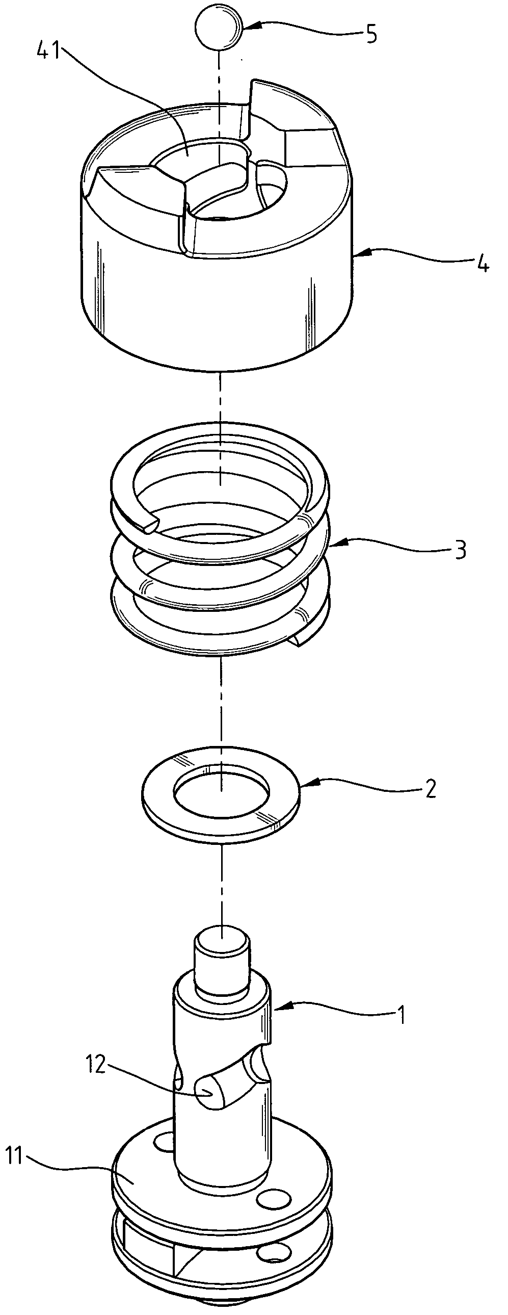
[0010] To attain the above-stated object, in a structure of shockproof spindle having a spindle inserted through an elastomer, a compressible structure, and a sleeve, a hollow and circular cylinder, sequentially. The sleeve caps the elastomer while the elastomer presses on the top of the base fixed under the spindle. The ball keeps contact the chute of the spindle and the chute of the sleeve. In addition to all of the above, the elastomer held between the base and the sleeve absorbs the impact when a tool installed on the end of the spindle is shocked against the workpiece during operation process.
[0011] The present invention has following improvements. First, the assembly process of the present invention is improved because the washer is a C-shaped plate and has an opening. The thickness of the washer can increase with this assembly process, and the thickness is greater the absorbing efficiency is better. Moreover, the design of the elastomer or the chute of the sleeve is not need to consider the interference between assembly of some parts, and the ball never drops from the chute of spindle. The present invention not only improves the impact absorbing efficiency but also prevents the damage of the transmission mechanism.

Problems solved by technology

These problems not only cause to lose function of impact absorbing but also destroy the transmission mechanism.

Method used


Image

  • Shockproof spindle
  • Shockproof spindle
  • Shockproof spindle

Examples


Embodiment Construction

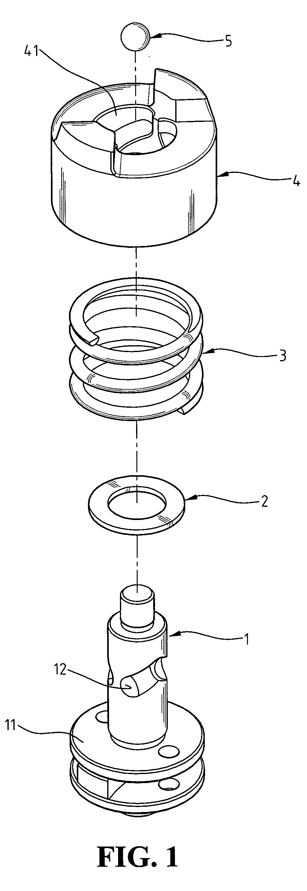
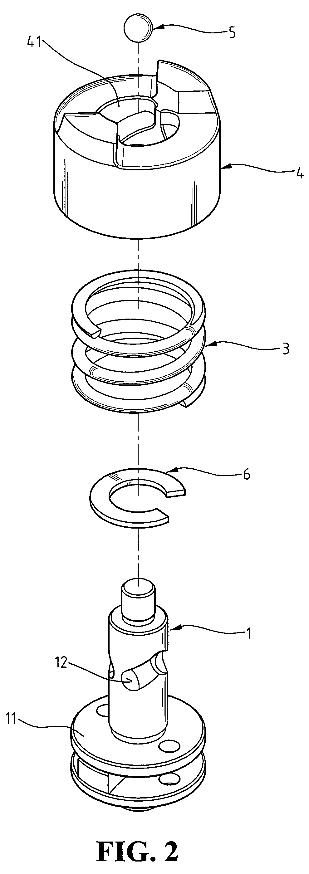
[0016] Referring to FIGS. 2 and 3, a shockproof spindle in accordance with the present invention comprises a spindle 1, a washer 6, an elastomer 3, a sleeve 4, and a ball 5.

[0017] The spindle 1 is a cylinder and installs coaxially on a base 11. The cylinder of the spindle 1 forms a chute 12 that is caved along the surface of the cylinder. The base 11 is also a cylinder and has an outer diameter which is greater than the spindle 1.

[0018] The washer 6 is a C-shaped plate made by elastic material and has a sufficient thickness. The opening size of the C-shaped plate, the washer 6, is according to the outer diameter of the spindle 1.

[0019] The elastomer 3 is a compressible structure, such as a compressive spring. The elastomer 3 surrounds the spindle 1 and contacts the upper face of the base 11.

[0020] The sleeve 4 is a hollow cylinder and has an inner surface forming an annular chute 41 that is caved along the inner surface of the upper port of the sleeve 4. The chute 41 holds a por...


PUM

PropertyMeasurementUnit
Deformation enthalpyaaaaaaaaaa

Abstract

A shockproof spindle includes a spindle inserted into an elastomer, a compressible structure, and a sleeve, a hollow cylinder, sequentially. The sleeve caps the elastomer while the elastomer presses on the top of the base fixed under the spindle. The ball keeps contact the chute of the spindle and the chute of the sleeve. In addition to all of the above, the elastomer held between the base and the sleeve absorbs the impact when a tool installed on the end of the spindle is shocked against the workpiece during operation process. Since the spindle works smoothly owing to the effect of the elastomer, the operators work more easily, and the damage or destruction of assembly precision, made by the impact, of the parts in the electric tool is avoided.

Description

BACKGROUND OF THE INVENTION [0001] 1. Field of the Invention [0002] The present invention relates to a structure of shockproof spindle, and more particularly to a structure that has a C-shaped washer, which has an opening to change the assembly process of the structure of spindle. Because of the new assembly process, a sleeve of the structure is able to modify its dimension to prevent falling of a ball guided in the structure under impact effect. In addition to all of the above, the thickness of the washer increases also, and that can improve the impact absorbing efficiency of the structure. [0003] 2. Description of Related Art [0004] A conventional structure of shockproof spindle is installed in an electric tool, such as an electric drill, for drilling cement wall, and has impact working function. The structure absorbs the impact when a tool installed on the end of the spindle is shocked against the workpiece during operation process. Since the structure works smoothly, the damage ...

Claims


Application Information

Patent Timeline
IPC IPC(8): B23P11/00B25D11/08B25D17/24E21B1/14
CPCB25D11/08B25D17/24B25D2222/57Y10T29/49842Y10T29/49872Y10T29/49826B25F5/006
Inventor CHEN, TING-KUANG
Owner POWER NETWORK IND
Learn More