
Extending the range of lithographic simulation integrals

a simulation integral and integral technology, applied in the field of optical microlithography, can solve the problems of reducing the range of lithographic simulation integrals, and ignoring the majority of scattered ligh

Active Publication Date: 2005-04-28
GLOBALFOUNDRIES US INC
View PDF17 Cites 28 Cited by
  • Summary
  • Abstract
  • Description
  • Claims
  • Application Information

AI Technical Summary

Benefits of technology

[0033] Still other objects and advantages of the invention will in part be obvious and will in part be apparent from the specification.

Problems solved by technology

Since present lithographic tools employ partially coherent illumination, such modeling is computationally intensive for all but elementary patterns.
Mathematical difficulties arise in optical proximity correction calculations that, in part, can be attributed to divergence issues when attempting to analytically express imaging kernels over the unbound sectors into which mask polygons are conventionally decomposed.
Second, even when the power spectrum of the wavefront is known or inferred, it is not possible to include the effect of high frequency wavefront components on an image integral that is truncated at a short ROI distance, causing most of the scattered light to be neglected.
Last, it is not straightforward to include these terms in the calculated image.

Method used


Image

  • Extending the range of lithographic simulation integrals
  • Extending the range of lithographic simulation integrals
  • Extending the range of lithographic simulation integrals

Examples


case 3

(case 3) as shown in FIG. 6, the triangle integral is given by L″(h,θ)=0, since the whole triangle is inside the hole of the kernel.

Rules for Sector Convolution

[0089] The polygon convolution method involves the calculation of the contribution from two triangles per vertex as previously mentioned and illustrated in FIG. 3. The triangle contributions give the net of the contribution of the polygon after summation through all vertices. Since the polygon can be of arbitrary shape and the observation point xo can be inside or outside the polygon, a rule for the sign of the contribution of each triangle is required. In most cases, lithographic mask patterns contain polygons formed by horizontal, vertical, and 45-degree line segments only. Therefore, an algorithm must handle 45-degree sectors in addition to 90-degree sectors. This makes for 96 possible types of sectors that may exist in any polygon. By taking into account the symmetry between the clockwise and counterclockwise vertex tra...


PUM


Abstract

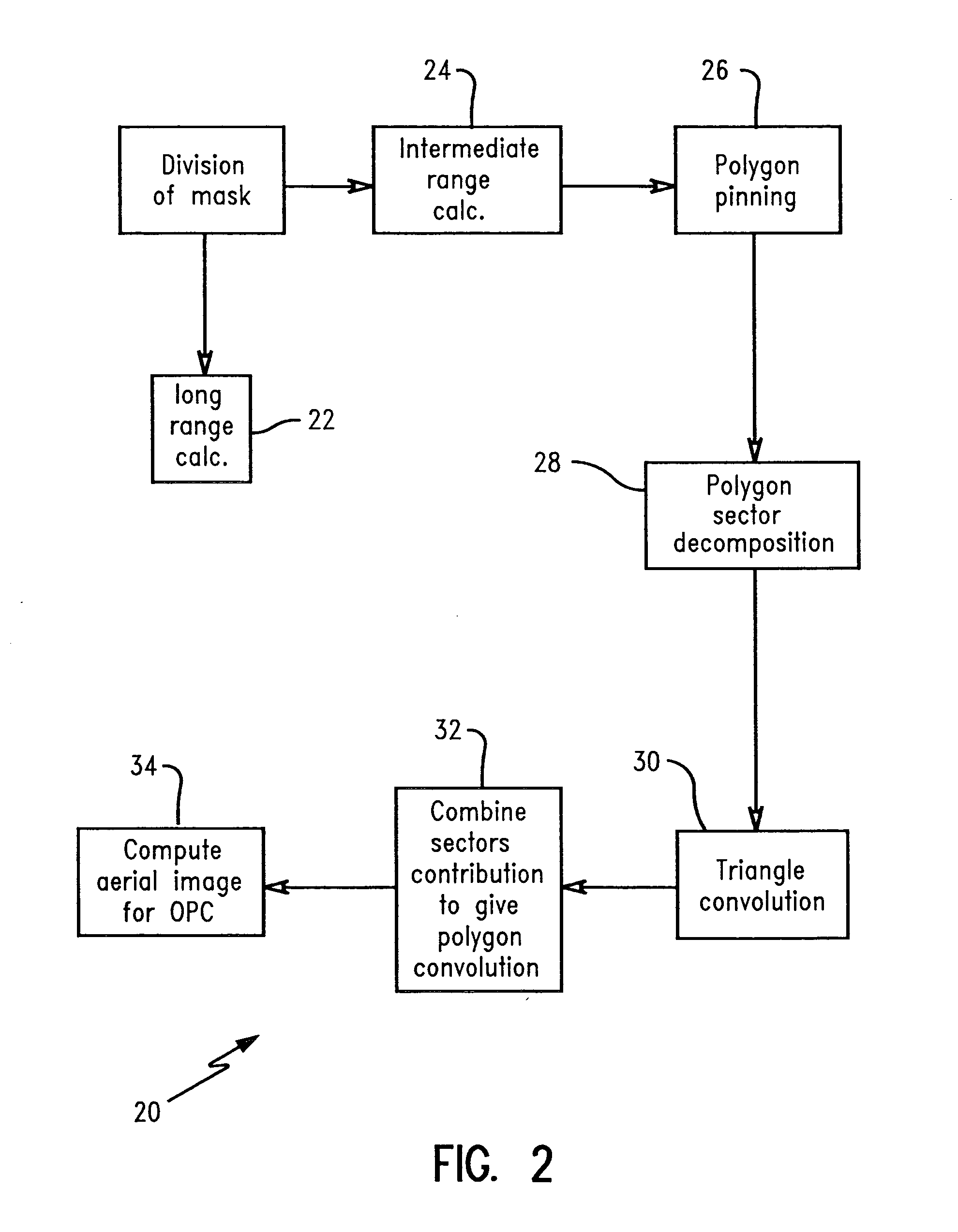
A method for calculating long-range image contributions from mask polygons. An algorithm is introduced having application to Optical Proximity Correction in optical lithography. A finite integral for each sector of a polygon replaces an infinite integral. Integrating over two triangles, rather than integrating on the full sector, achieves a finite integral. An analytical approach is presented for a power law kernel to reduce the numerical integration of a sector to an analytical expression evaluation. The mask polygon is divided into regions to calculate interaction effects, such as intermediate-range and long-range effects, by truncating the mask instead of truncating the kernel function.

Description

CROSS-REFERENCE TO RELATED APPLICATIONS [0001] The present application is related to commonly assigned U.S. patent application Ser. No. ______ (Attorney Docket No. FIS920030108, titled “INCORPORATION OF A PHASE MAP INTO FAST MODEL-BASED OPTICAL PROXIMITY CORRECTION SIMULATION KERNELS TO ACCOUNT FOR NEAR AND MID-RANGE FLARE”), U.S. patent application Ser. No. ______ (Attorney Docket No. FIS920030109, titled “IMPROVEMENT OF PERFORMANCE IN SECTOR-BASED OPC ENGINE UTILIZING EFFICIENT POLYGON PINNING METHOD AND SIMULTANEOUS COMPUTATION OF MULTIPLE SAMPLE POINTS”), U.S. patent application Ser. No. ______ (Attorney Docket No. FIS920030110, titled “RENESTING INTERACTION MAP INTO DESIGN FOR EFFICIENT LONG RANGE CALCULATIONS”), and U.S. patent application Ser. No. ______ (Attorney Docket No. FIS920030262, titled “SIMULTANEOUS COMPUTATION OF MULTIPLE POINTS ON ONE OR MULTIPLE CUT LINES”), filed on even date herewith, which are hereby incorporated by reference herein in their entirety.BACKGROUN...

Claims


Application Information

Patent Timeline
IPC IPC(8): G03F1/08G03F1/14H01L21/027
CPCG03F1/36G03F1/144G03F1/70
Inventor GALLATIN, GREGG M.GOFMAN, EMANUELLAI, KAFAILAVIN, MARK A.MUKHERJEE, MAHARAJRAMM, DOVROSENBLUTH, ALAN E.SHLAFMAN, SHLOMO
Owner GLOBALFOUNDRIES US INC
Learn More