Method of observing defects

Inactive Publication Date: 2005-04-28
HITACHI HIGH-TECH CORP
View PDF10 Cites 17 Cited by
  • Summary
  • Abstract
  • Description
  • Claims
  • Application Information

AI Technical Summary

Benefits of technology

[0017] More specifically, in a step of irradiating a convergent electron beam to the defects to be observed, detecting an electron emitted from surfaces of the defects to be observed, and acquiring a planar image, the inclined image-taking direction is automatically decided from the images of the detected electrons and an inclined review image is automatically taken. The direction in which the convergent electron beam is irradiated may be controlled with respect to the defects to be observed by deflecting the convergent electron beam relative to the decided direction through an electron beam deflector so as to displace them from an optical axis. Additionally, the electron emitted from each surface of the defects to be observed is detected by a secondary electron detector and a back-scattered electron detector simultaneously in order to be able to quickly shift the inclined image-taking direction and implement each three-dimensional profile of the defects to be observed.
[0018] Thus, according to the invention, it is possible to automatically decide the direction of inclined observation and take (pick up) the inclined review image so that the inclined images can be taken automatically on a batch processing with the minimal efforts.

Problems solved by technology

For example, the above-described conventional techniques are inconvenient to the inclined observation and it has been particularly difficult to utilize the inclined observation in mass production lines.
The above-mentioned problem of the observation of the inclined images, using the method of deflecting the electron beams irradiated from the electronic optical system and changing a irradiated direction of the electron beam, makes it difficult to extrapolate a three-dimensional profile of the object if the object does not have a clearly edged structure and the three-dimensional profile of the objects of images to be taken is modestly changed.
In such small inclination angle, appearances of the object viewed after the modest three-dimensional profile change are hardly changed, so that it is difficult to acquire useful information on the profile.

Method used


Image

  • Method of observing defects
  • Method of observing defects
  • Method of observing defects

Examples


Embodiment Construction

[0036] Hereinafter, embodiments of the present invention will be detailed based on the accompanying drawings. Note that members having the same function are denoted by the same reference numeral throughout all the drawings for describing the embodiments and the repetitive explanation thereof will not be omitted.

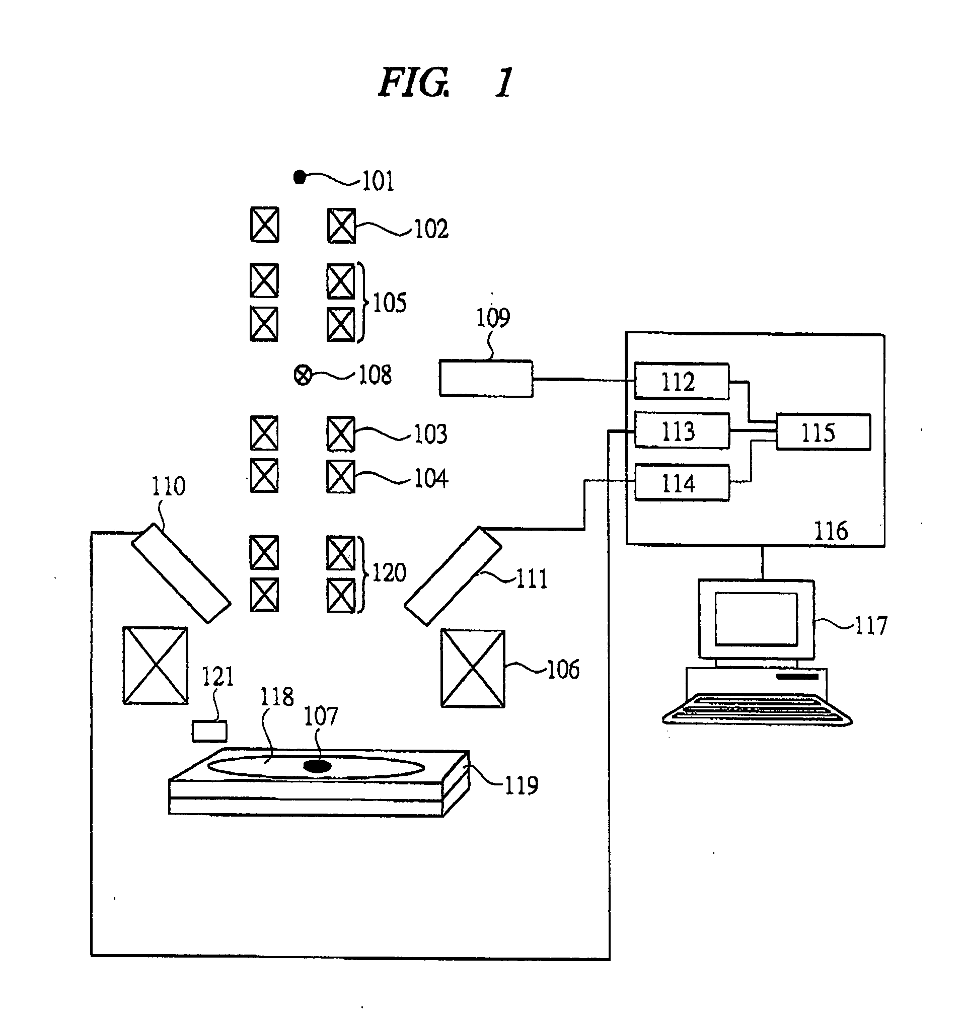
[0037] First, an example of a defect observing system for implementing a defect observing method according to the present invention will be described with reference to FIG. 1. FIG. 1 is a block diagram of a defect observing system of the present embodiment.

[0038] With the illustrated defect observing system, electron beams are irradiated from an electron-beam source 101 and the irradiated electron beams are made to pass through a condenser lens 102 and subsequently deflected by scanning units 103 and 104 so as to control the spot to be irradiated by the electron beams. Deflection units 105 and 120 control irradiation angles of the electron beams to an object. Then, the elec...


PUM


Abstract

This invention provides a technique for observing defects, which can automatically decide a direction from inclined observation and take an inclined review image. In a defect observing system for detecting the defects and thereafter observing images of the defects from various directions in detail, positions of inclined images to be taken are automatically displayed on a display screen from a planar image (top-down image) of a SEM using CAD data, and the defects are selected from the images displayed on the display screen based on specification by a user, an inclined angle and direction are determined per selected image to take an inclined image (beam-tilt image), and the inclined image of each defect is acquired.

Description

CROSS-REFERENCE TO RELATED APPLICATION [0001] The present application claims priority from Japanese patent application No. JP 2003-345447 filed on Oct. 3, 2003, the content of which is hereby incorporated by reference into this application. BACKGROUND OF THE INVENTION [0002] The present invention generally relates to a technique for automatically observing defects of industrial products and more particularly to a technique effectively applied to a method of easily observing from various directions images of defects after pre-process detection of semiconductor products, the pre-process detection being important to detailed observation of the defects that has already been detected. [0003] As a result of examinations by the inventors of the present invention, the following techniques are conceivable for observing defects. [0004] For example, as semiconductors are miniaturized, it has become increasingly difficult to execute pre-process control in a manufacturing process of the semicond...

Claims


Application Information

Patent Timeline
IPC IPC(8): G01N23/225G06T1/00G21K7/00H01J37/20H01L21/66
CPCG01N23/2251H01J2237/2817H01J2237/2815H01J2237/2814
Inventor HONDA, TOSHIFUMIKUBO, TOSHIRO
Owner HITACHI HIGH-TECH CORP
Why Eureka
Try Eureka