
Distributed connection-oriented services for switched communication networks

a technology of switched communication network and service, applied in the direction of data switching network, data switching details, instruments, etc., can solve the problems of large bandwidth consumption of multimedia and full-motion video applications, requiring real-time delivery, and sharing media network cannot provide the high bandwidth and quality of service required by the latest networking application and new faster workstations

Inactive Publication Date: 2005-04-21
EXTREME NETWORKS INC
View PDF89 Cites 96 Cited by
  • Summary
  • Abstract
  • Description
  • Claims
  • Application Information

AI Technical Summary

Benefits of technology

[0036] One of the significant benefits of determining connections based on the source-destination MAC addresses is that it allows the switches to treat each end-to-end flow as a unique and identifiable connection (flow). In addition, it allows the switches to support a fully active mesh topology. Unlike switches that forward or filter based only on the destination MAC address, the switches of the present invention use the source and destination MAC address in each frame to forward or filter. This allows multiple paths to a particular destination from different sources through the switch fabric. This is particularly useful in client / server models, because the server is effectively a common point, to which all the clients require access. Thus, the call processing of the present invention allows, multiple paths to the server from different sources through the switch fabric.

Problems solved by technology

A router-based, shared-media network cannot provide the high bandwidth and quality of service required by the latest networking applications and new faster workstations.
For example, multimedia and full-motion video applications consume large amounts of bandwidth and require real-time delivery.
Thus, networks once used primarily for sending text files and E-mail or sharing common databases, are now being pushed to their limits as more users push more data across them.
One way to provide additional bandwidth on a given network segment is with larger shared-media pipes, such as FDDI or Fast Ethernet; however, this does not enable the application of policy or restricted access to the enhanced network resources.
Alternatively, a network can be further segmented with additional router or bridge ports; however, this increases the cost of the network and the complexity of its management and configuration.
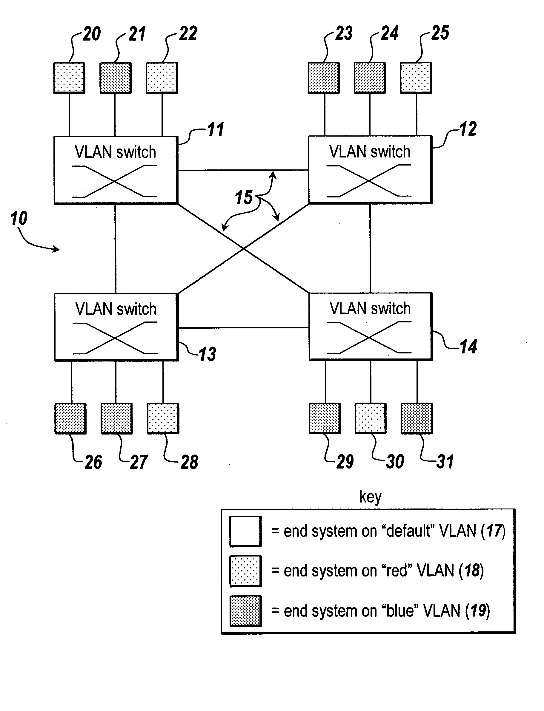
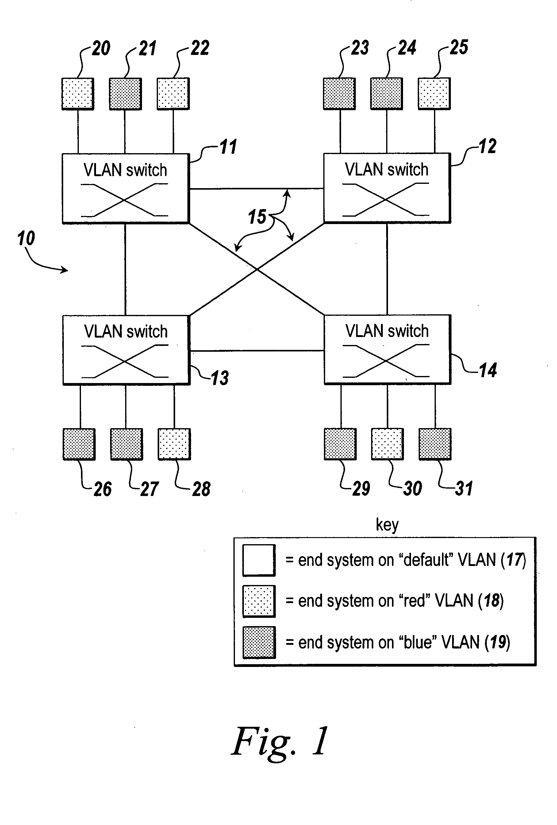
However, many VLAN implementations restrict VLAN assignments to ports, rather than end systems, which limits the effectiveness of the VLAN groupings.
Other limitations of existing VLAN implementations include excessive broadcast traffic (which consume both network bandwidth and end system CPU bandwidth), disallowing transmissions out multiple ports, hop-by-hop switching determinations, and requiring multi-protocol routers to enable transmission between separate VLANs.
Another problem with many VLAN switched networks is that although they allow a meshed topology, none of the redundant links can be active at the same time.
Unfortunately, any links or nodes not in the active tree path are placed in standby.
Thus, there are numerous limitations with many prior switched communications networks.

Method used


Image

  • Distributed connection-oriented services for switched communication networks
  • Distributed connection-oriented services for switched communication networks
  • Distributed connection-oriented services for switched communication networks

Examples


example

[0177] As illustrated in FIG. 8, a path select request may be made at a call-originating switch X1 (50), for a destination switch X5 (54). The protocol returns the best (meaning lowest aggregated metric) path to X5. This would be the path “e,d” (through switch X4 (53)), assuming like media and default metric assignments. Path “e,d” has a value of 10. Path “a,b,c” (through switches X2 (51) and X3 (52)) has value of 15 and would not be chosen. Should link “e” fail, the path “a,b,c” would take over and continue to provide connectivity. Should the value of the metric be manipulated such that path “a,b,c” and path “e,d” were of equal value, the protocol would return both to the path selection request.

[0178] In the flow state diagrams of FIGS. 9-11, describing the state machines for the ingress, intermediate and egress switching functions, the following conventions apply: [0179] any text in italic represents a variable used in the description; [0180] Cnx is an abbreviation for a connecti...

example ip topology

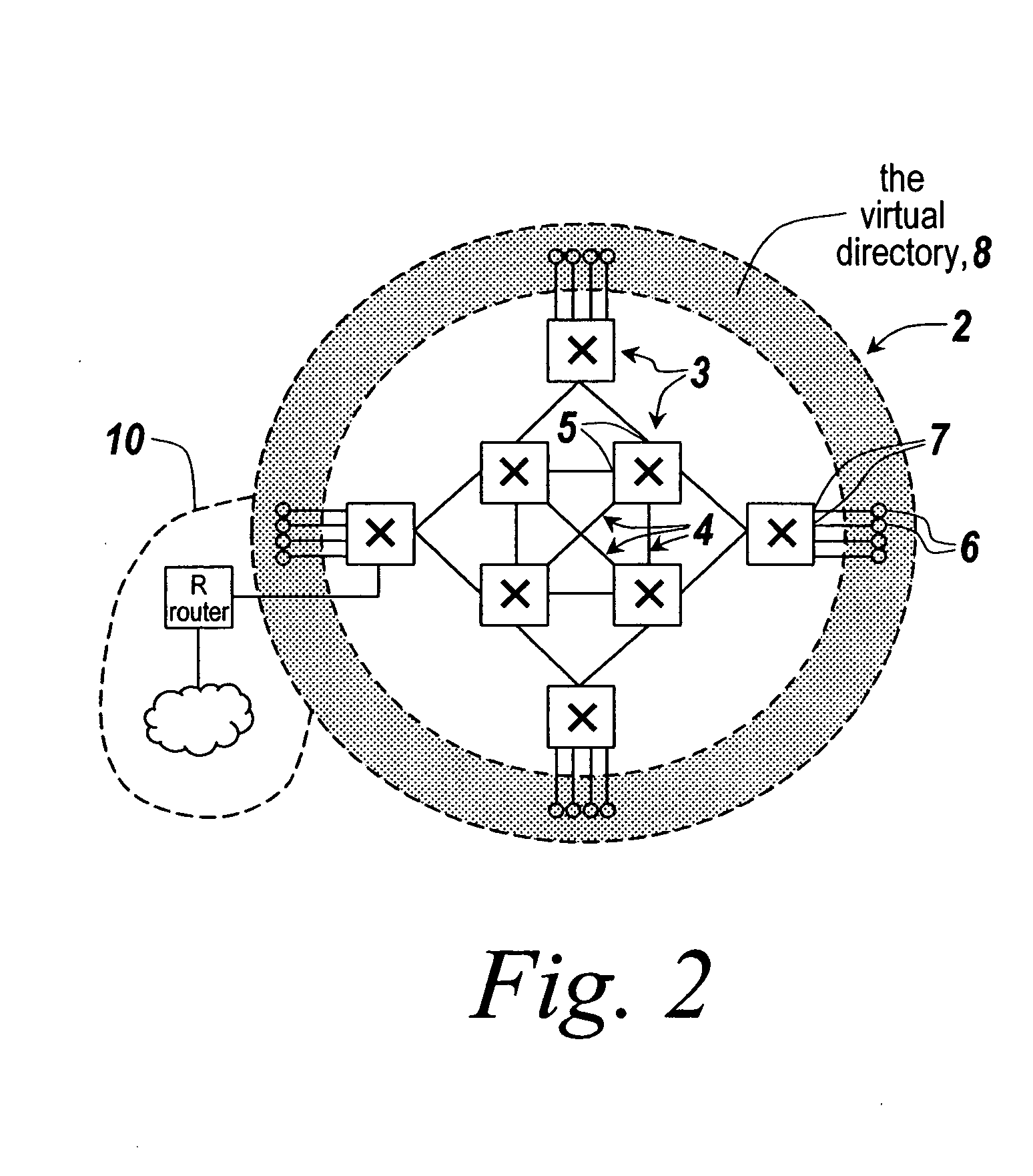
[0232]FIG. 21 depicts an example IP network topology employing SFRS, which includes IP Hosts interconnected by routers and access switches and which covers the 134.141.0.0 network. The network is subnetted using the mask 255.255.255.0. There are four IP subnets shown. The switch backbone (220) is comprised of the 134.141.41.0 and 134.141.43.0 subnets. Two of the other subnets are found behind edge routers; 134.141.50.0 subnet (228) behind Router A (224), and 134.141.90.0 subnet (229) behind Router B (225). Access switches 1-3 (221-223) discover the IP routes via broadcasts within the IP broadcast group of the switch domain. IP routers advertise the reachability of networks by using IP RIP or OSPF. These advertisements are also collected and periodically resent.

[0233] The following IP RIP routing tables are for access switches 1-3:

Access Switch 1 IP Routing Table

[0234]

IP NetworkHopsNHopNetTypeLocation134.141.41.000.0.0.0StaticInternal134.141.43.000.0.0.0StaticInternal

Access Switch...


PUM


Abstract

Method and apparatus providing connection-oriented services for packet switched data communications networks. Directory services include distributed discovery of MAC addresses and protocol alias addresses. Topology services include a link state topology exchange among switches, which provides each switch with a complete topology graph of the network. This enables an access switch receiving a data packet to determine a complete path from a source end system to a destination end system. Another service includes resolution of broadcast frames to unicast frames, in order to reduce the amount of broadcast traffic. Policy restrictions may be applied prior to connection setup. Path determination services enable multiple paths from a source to a destination. Connection management includes source routed mapping of connections on the desired path. A distributed call rerouting service is provided wherein if a link on an active path fails, each switch receives a topology change notification and unmaps any connection involving the failed link. A broadcast / unknown service provides restricted flooding of nonresolvable packets. Furthermore, connection-oriented switching is provided based on the source and destination MAC addresses as a connection identifier. Still further, resolution of networks outside the switch domain is enabled by access switches listening for network and server route advertisements and maintaining best routes to said networks and servers. The best route metrics may be combined with best path metrics to determine a path from a first access switch to an egress switch connected to the external network.

Description

RELATED APPLICATIONS [0001] This is a continuation-in-part of copending and commonly owned U.S. Ser. No. 08 / 559,738 filed Nov. 15, 1995 entitled “METHOD FOR ESTABLISHING RESTRICTED BROADCAST GROUPS IN A SWITCHED NETWORK,” by K. Dobbins et al., which is hereby incorporated by reference in its entirety.FIELD OF THE INVENTION [0002] This invention relates to various methods and apparatus which provide distributed connection-oriented services for switched data communications networks, the services provided being scalableable, allowing fully active mesh topologies, reducing broadcast traffic, and enabling connections to networks and servers outside the switch domain. BACKGROUND OF THE INVENTION [0003] Most data communications networks today rely heavily on shared-media, packet-based LAN technologies for both access and backbone connections. These networks use bridges and routers to connect multiple LANs into global internets. [0004] A router-based, shared-media network cannot provide the...

Claims


Application Information

Patent Timeline
Patent Type & Authority Applications(United States)
IPC IPC(8): H04L12/18H04L12/24H04L12/46H04L12/56
CPCH04L12/18H04L2212/0025H04L12/1886H04L12/46H04L12/4641H04L12/467H04L41/0213H04L45/04H04L45/16H04L45/24H04L45/34H04L49/201H04L49/351H04L49/354H04L12/1877H04L2212/00H04L41/40
Inventor DOBBINS, KURTGRANT, THOMAS A.RUFFEN, DAVID J.KANE, LAURALEN, THEODOREANDLAUER, PHILIPBAHI, DAVID H.YOHE, KEVINFEE, BRENDANOLIVER, CHRISCULLEROT, DAVID L.SKUBISZ, MICHAEL
Owner EXTREME NETWORKS INC
Learn More