Mechanism type non-sectional locking buffer device

a buffer device and mechanism technology, applied in the field of buffer devices, can solve the problems of relatively high cost, complex oil pressure buffer mechanism, injury to the vertebra of children or elderly people, etc., and achieve the effect of slowing down a jolting force and reducing the malfunction of the buffer

Inactive Publication Date: 2005-04-21
PRO GLORY ENTERPRISES
View PDF7 Cites 3 Cited by
  • Summary
  • Abstract
  • Description
  • Claims
  • Application Information

AI Technical Summary

Benefits of technology

[0007] Inner screw grooves are configured on an inner wall of a buffer chamber, thereof providing grooves for the ball bearings of the central shaft to slip therein, and utilizing a screw ascending descending principle as a buffering function, thereby slowing down a jolting force from repositioning or returning of an upright support, and reducing buffer malfunction thereof.

Problems solved by technology

However, returning of an upright support utilizes an almost instant restoring force of the spring, and while this force does not constitute a danger to an adult, nevertheless, the jolting force from repositioning or returning of an upright support can easily cause injury to vertebra of children or elderly persons.
However, an oil pressure buffer mechanism is relatively intricate, thus cost is relatively high, moreover, there is an apprehension of leaking oil.
Upon a traffic vehicle catching fire because of outside influences, oil can foster rapid fire destruction of the traffic vehicle.

Method used


Image

  • Mechanism type non-sectional locking buffer device
  • Mechanism type non-sectional locking buffer device
  • Mechanism type non-sectional locking buffer device

Examples


Embodiment Construction

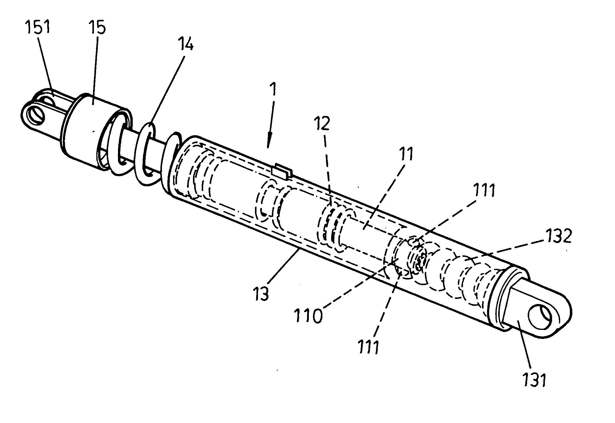
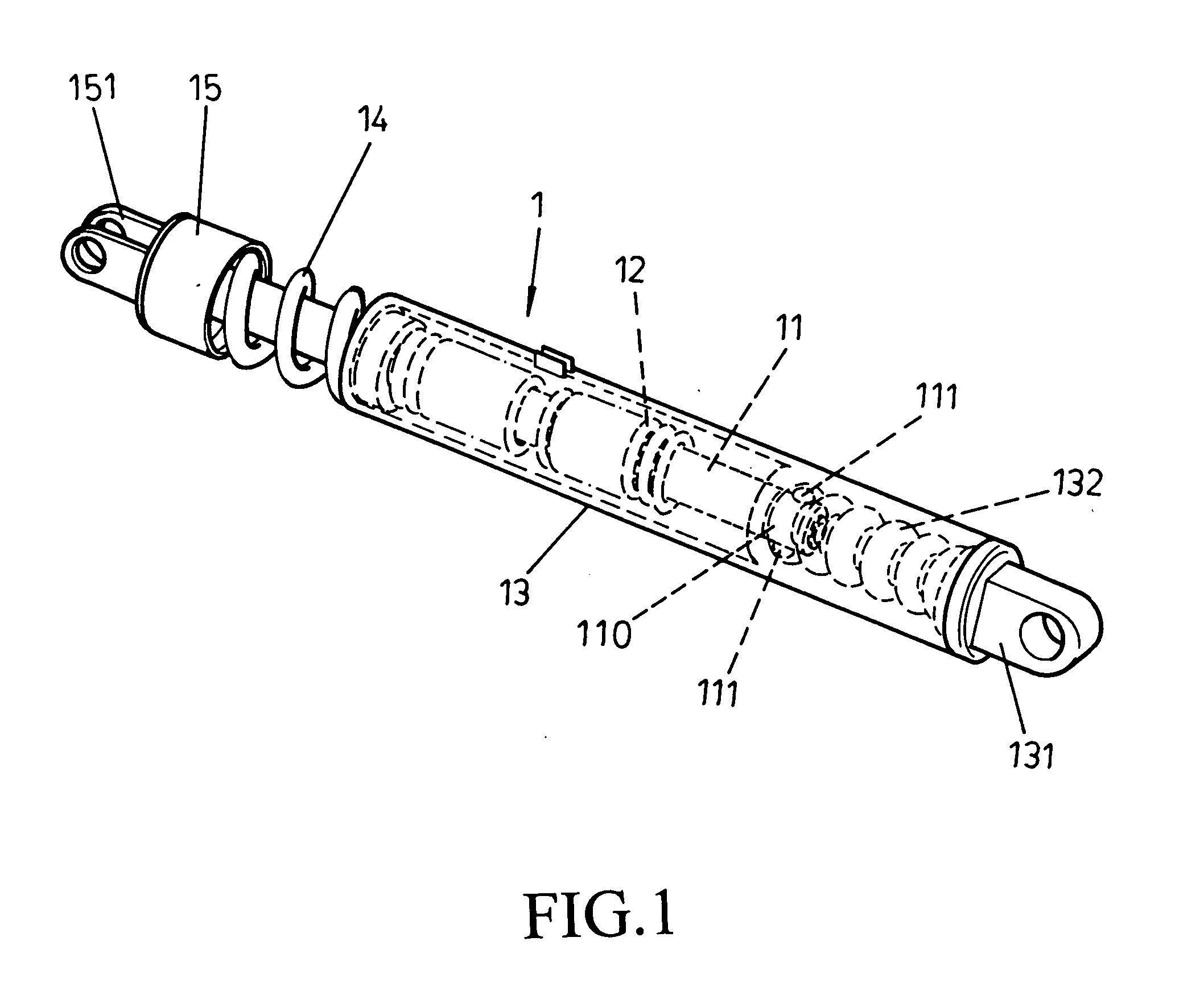
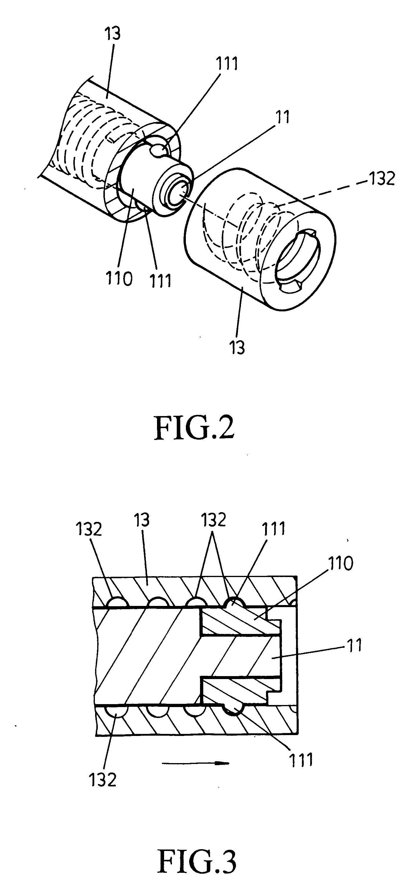
[0014] Referring to FIGS. 1, 2 and 3, which show one embodiment of the present invention installed below a chair cushion seat, and described hereinafter. A buffer 1 is assembled from structural elements comprising a central shaft 11, a torsion spring 12, a buffer chamber 13, a reposition spring 14 and a spring collar 15, wherein the torsion spring 12 is configured on the outer edge of the central shaft 11. The central shaft 11 and the torsion spring 12 are together disposed in the buffer chamber 13. A fixing mount 131 of one end of the buffer chamber 13 is enabled to bolt to a chair-back using a screw bolt, securely fixing thereof. Another end of the buffer chamber 13 is connected to the reposition spring 14, and another end of the reposition spring 14 engages with the spring collar 15. Securing lugs 151 of one end of the spring collar 15 bonds to a chair cushion frame thereof. The present invention is characterized in having:

[0015] More than one ball bearing 111 is configured on t...


PUM


Abstract

A non-sectional locking buffer device. The device utilizes a screw ascending and descending principle as a buffering function, wherein ball bearings or outer screw grooves are configured on a central shaft of the buffer device to operate in coordination with inner screw grooves or ball bearings configured on an inner wall of a buffer chamber. The inner and outer screw mechanisms rely on slippage of the ball bearings in the screw grooves, to reduce a jolting force from repositioning or returning of an upright support, thereby reducing buffer malfunction.

Description

BACKGROUND OF THE INVENTION [0001] (a) Field of the Invention [0002] The present intention relates to a buffer device applicable for use in seats of traffic vehicles, grips used by handicapped, etc. Upon a chair-back or grip returning to a perpendicular state from an inclined state, the buffer device utilizes a mechanical screw type principle as a buffer function. In addition to averting injury from a jolting force from repositioning or returning of an upright support, also reduces buffer malfunction. [0003] (b) Description of the Prior Art [0004] Regarding a buffer structure of a conventional seat, a conical spring is configured within a buffer compartment, whereby one end clamps to a chair-back upright, and one end fastens to a frame of a chair seat, therewith utilizing a restoring force of the spring to allow a sitter to avail himself of an ascending descending buffer to lighten a load on vertebra of the sitter caused by a force from sitting-down. However, returning of an upright...

Claims


Application Information

Patent Timeline
Patent Type & Authority Applications(United States)
IPC IPC(8): B60G13/00F16F5/00F16F7/09F16F13/00
CPCF16F7/09F16F2232/06F16F2230/0041F16F13/005
Inventor LUNG, CHING-YUNGSU, YUN-CHIN
Owner PRO GLORY ENTERPRISES
Why Eureka
Try Eureka