
Mass spectrometer

a mass spectrometer and mass spectrometer technology, applied in the field of mass spectrometers, can solve the problems of large data storage capacity and difficulty in linear flight distance, and achieve the effects of reducing the memory area, reducing the cost of data processing devices, and reducing the quantity of data

Active Publication Date: 2005-04-14
SHIMADZU CORP
View PDF3 Cites 15 Cited by
  • Summary
  • Abstract
  • Description
  • Claims
  • Application Information

AI Technical Summary

Benefits of technology

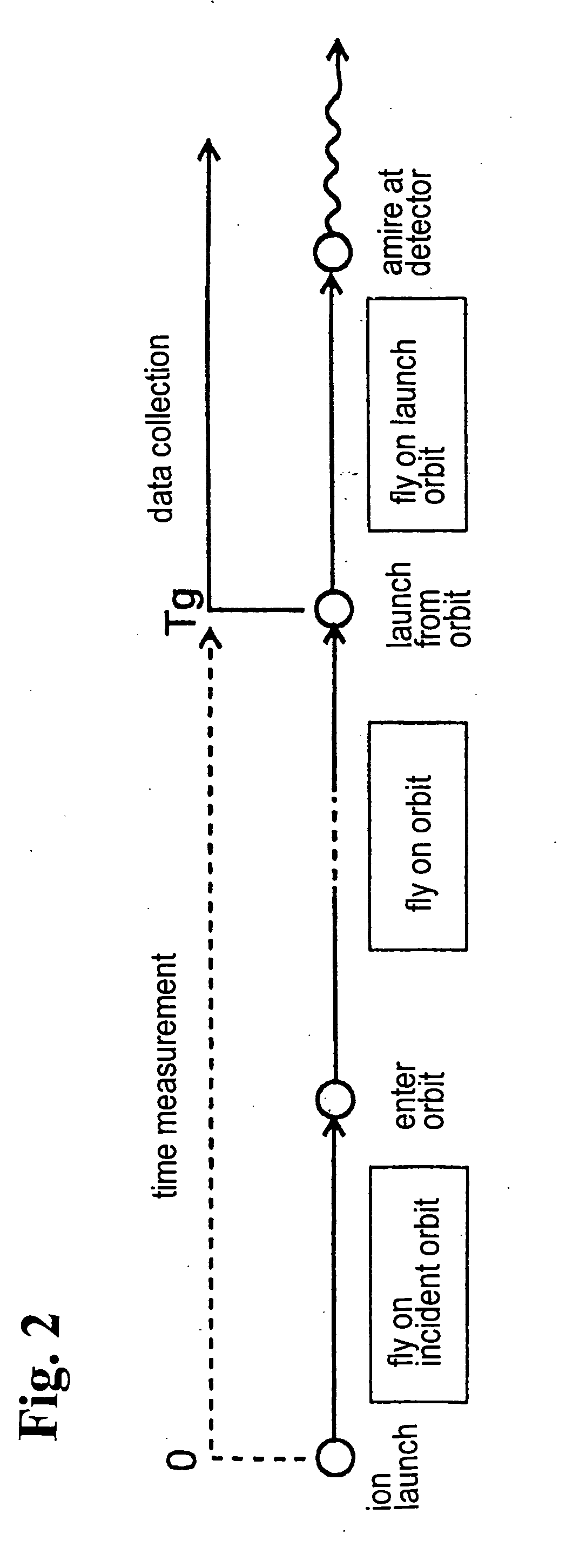
[0016] According to the mass spectrometer of the invention, it is not necessary to collect the data during a large portion of the period when the detecting signal has no change until the ions arrive at the detector. Accordingly, as compared with a case where the data are collected from the time point when the ions are launched, it is possible to greatly reduce a memory area for storing the collected data, thereby reducing cost of the data processing device. With the reduced data quantity, it is also possible to reduce a load of processing data. Of course, even if the data quantity is reduced as described above, the accuracy and sensitivity of the analysis are not impaired.

Problems solved by technology

However, it is generally difficult to provide a long flight distance linearly due to limitation in a size of a device.
Accordingly, it is necessary to collect a large amount of the data, thereby requiring a large capacity for storing the data.

Method used


Image

  • Mass spectrometer
  • Mass spectrometer
  • Mass spectrometer

Examples


Embodiment Construction

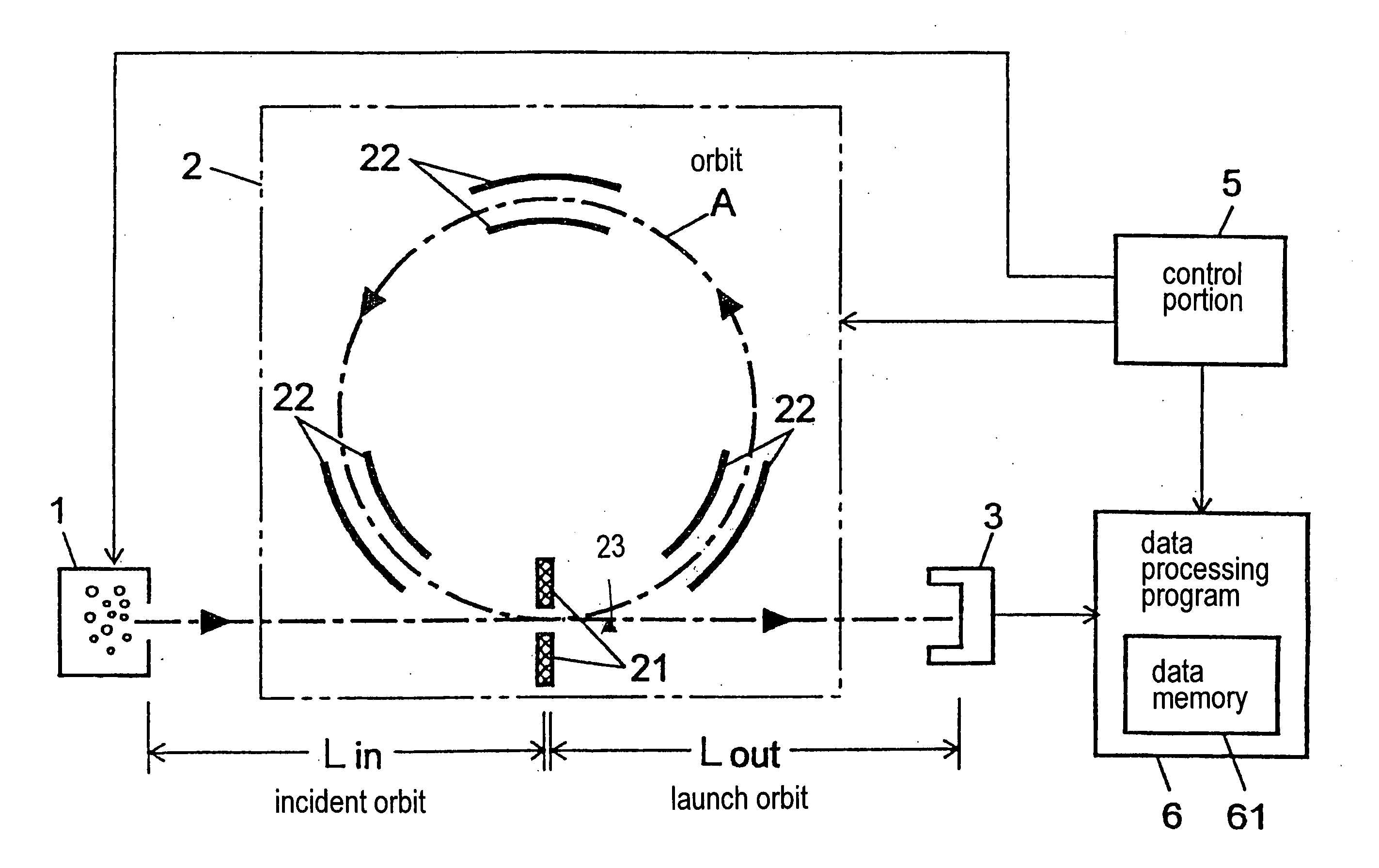
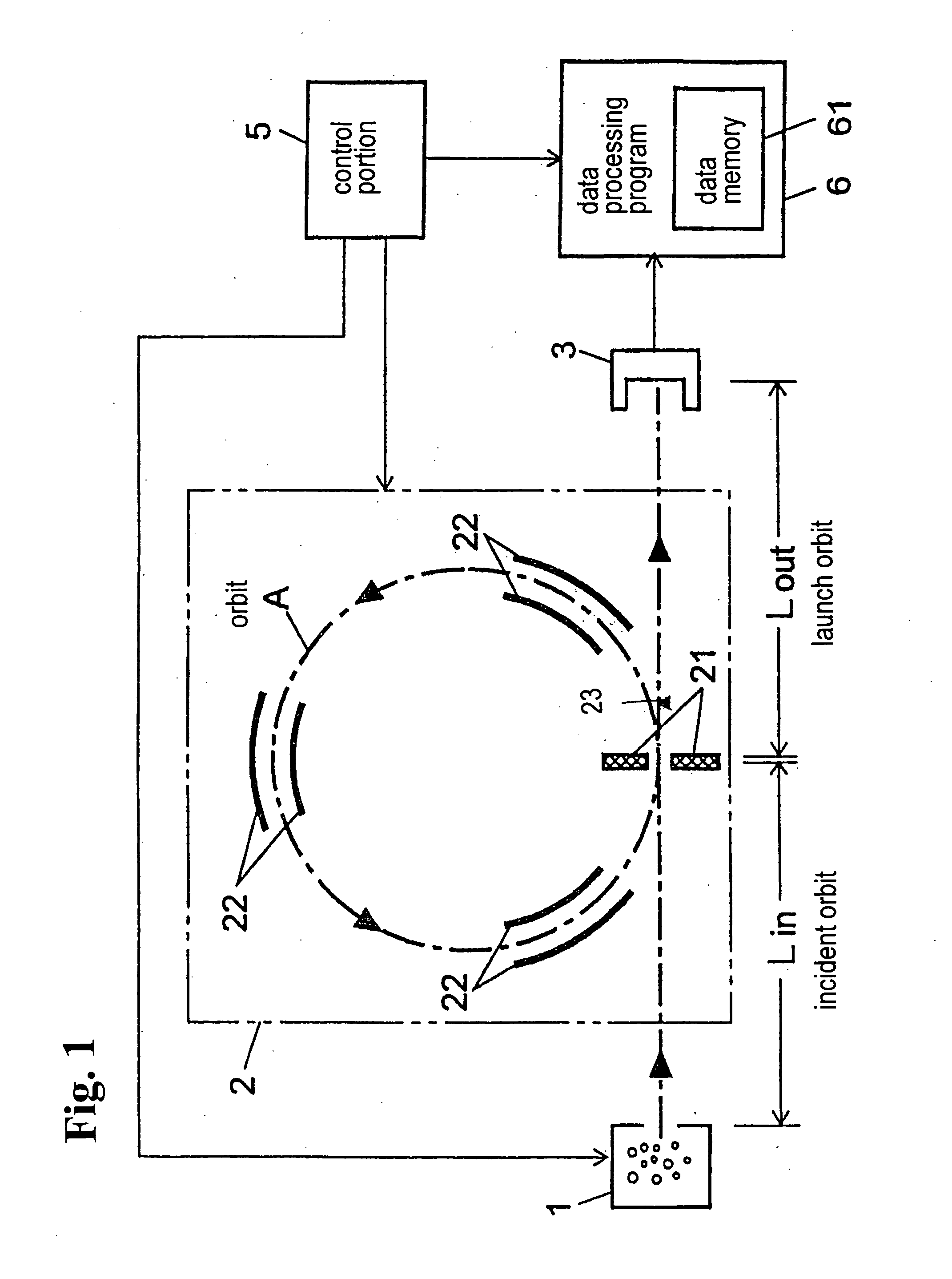
[0020] Hereunder, embodiments of the present invention will be explained with reference to the accompanying drawings. FIG. 1 is a block diagram showing a mass spectrometer according to an embodiment of the present invention. In FIG. 1, an ion source 1, a flight space 2, and an ion detector 3 are disposed in a vacuum chamber (not shown).

[0021] The ion source 1 ionizes molecules to be analyzed, and an ionizing method is not limited to a specific one. For example, when the mass spectrometer of the invention is used for GC / MS, the ion source 1 may ionize gas molecules with electron ionization method or chemical ionization method. When the mass spectrometer is used for LC / MS, the ion source 1 may ionize liquid molecules with atmospheric pressure chemical ionization method or electrospray ionization method. When molecules to be analyzed are macromolecules such as a protein, matrix assisted laser desorption ionization (MALDI) method may be used.

[0022] The flight space 2 includes therein ...


PUM

PropertyMeasurementUnit
mass spectrometeraaaaaaaaaa
ion strengthaaaaaaaaaa
voltageaaaaaaaaaa

Abstract

A mass spectrometer includes a flight control device for allowing ions from an ion source to repeatedly fly along an orbit in a flight space for predetermined times; a detecting device for detecting the ions after the ions repeatedly fly along the orbit for the predetermined times; and a data processing device for starting collection of ion strength data detected by the detecting device. The ion strength data is obtained during the flight of the ions along the orbit, or when the ions are headed toward the detecting device after departing from the orbit, or when one of the above situations is estimated.

Description

BACKGROUND OF THE INVENTION AND RELATED ART STATEMENT [0001] The invention relates to a mass spectrometer, more specifically, a mass spectrometer having a flight space wherein ions to be analyzed make orbital movements or reciprocal movements on a substantially same orbit. [0002] In a Time of Flight Mass Spectrometer (hereinafter referred to as “TOFMS”), generally, ions accelerated by an electric field are introduced into a flight space having no electric field nor magnetic field, and various ions are separated by a mass number according to a flight time until the ions reach a detector. A difference in the flight time between two different ions having different mass numbers increases as the flight time increases. Accordingly, a long flight distance is preferable in order to improve resolution in the mass number. However, it is generally difficult to provide a long flight distance linearly due to limitation in a size of a device. Conventionally, various structures have been proposed ...

Claims


Application Information

Patent Timeline
Patent Type & Authority Applications(United States)
IPC IPC(8): G01N27/62H01J49/06H01J49/10H01J49/40
CPCH01J49/408H01J49/0036
Inventor YAMAGUCHI, SHINICHIISHIHARA, MORIOTOYODA, MICHISATO
Owner SHIMADZU CORP
Learn More