
Pressure container manufacturing method

Active Publication Date: 2005-04-14
SUBARU CORP
View PDF5 Cites 29 Cited by
  • Summary
  • Abstract
  • Description
  • Claims
  • Application Information

AI Technical Summary

Benefits of technology

[0010] The present invention is developed in view of the above described problems, and an object of the present invention is to provide a pressure container manufacturing method in which a pressure container which has a high strength and is light in weight can be obtained while suppressing the manufacturing cost, and a pressure container manufactured by the manufacturing method.
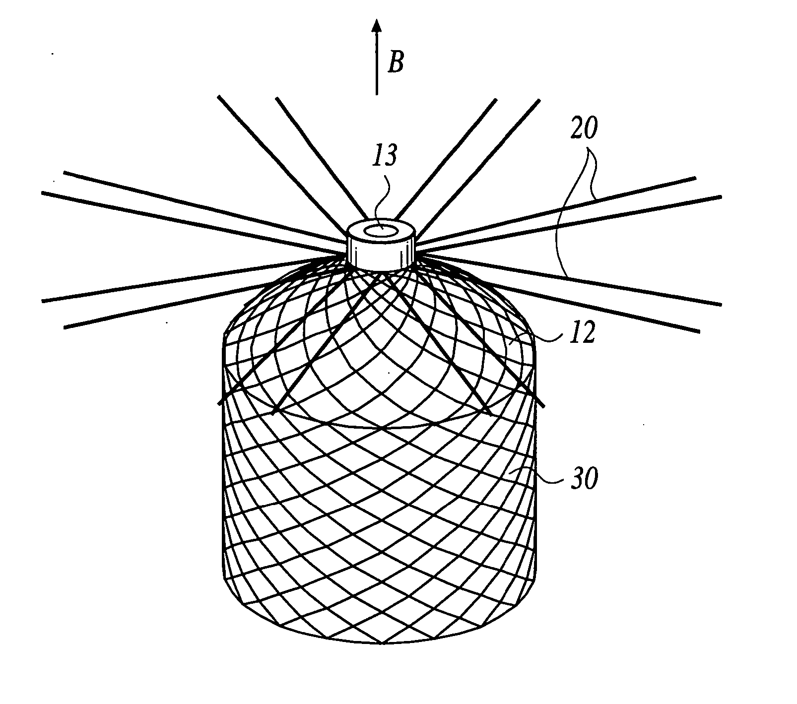
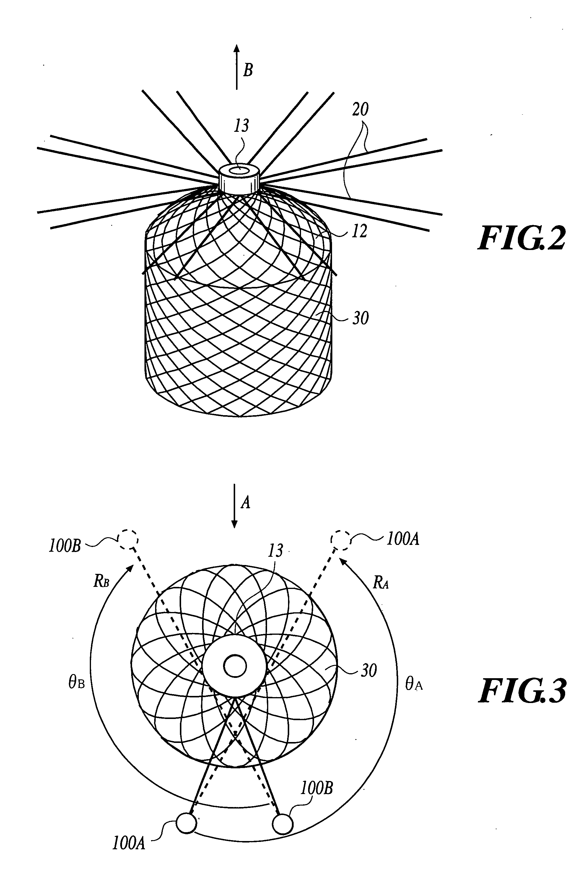
[0013] For this reason, like the helical winding system of the FW method, the braiding can be carried out in such a way that the fiber bundles are wound to the dome portion of the liner, eliminating the need to cut off the fiber bundles or alternatively the need to crook the fiber bundles so as to be folded back when reversing the moving direction of the liner. As a result, it is possible to reinforce the strength of the outer shell of the fiber reinforced composite material, further making it possible to reinforce the strength of the tank.
[0014] According to the method of the first aspect of the invention, when forming the body on the outer periphery of the liner by providing the fiber bundles from the bobbins of the braider while moving the liner in an axial direction, a movement in a first direction of the liner is stopped when the forming position reaches the root portion of the mouth piece of the liner. The formation of the liner is continued by moving the liner in a second direction opposite to the first direction after each of the bobbins are rotated approximately a half-turn. Therefore, when reversing the moving direction of the liner, the need to cut off the fiber bundles, or alternatively the need to crook greatly the fiber bundles so as to be folded back, is eliminated. As a result, the strength of the outer shell made of a fiber reinforced composite material is reinforced, further making it possible to obtain a pressure container with a high strength while taking full advantage of the merits of the braiding method (i.e. short manufacturing time and low manufacturing cost).

Problems solved by technology

Earlier, a pressure container made of metal which has a high strength and is excellent in gas barrier property has been mainstream, however due to its heavy weight, there is a difficulty in applying it to a fuel tank of an automobile or a space plane in which weight saving is required.
However, applying the FW method would raise a problem of requiring a long period of time to wind the tow-shaped prepreg on the liner.

Method used


Image

  • Pressure container manufacturing method
  • Pressure container manufacturing method
  • Pressure container manufacturing method

Examples


Embodiment Construction

[0019] The embodiment of the present invention will be explained hereinbelow referring to the drawings.

[0020] In the embodiment, the explanation will be made on a method to manufacture a CNG tank by forming an outer shell made of a fiber reinforced composite material on the outer periphery of the liner 10 (refer to FIG. 1). The tank manufactured by the method according to this embodiment is a pressure container which can be filled with several hundred of atmospheres of gas.

[0021] First, the liner 10 is molded by a material which is excellent in gas barrier property (liner molding step). In the embodiment, the liner 10 is molded by a blow molding method using a liquid crystal resin which is superior in dimensional stability and chemical resistance as well as gas barrier property. The liner 10, as shown in FIG. 1, comprises a cylindrical portion 11 and dome portions 12 formed at both ends of the cylindrical portion 11. A metal mouth piece 13 is attached to the top of each dome porti...


PUM

PropertyMeasurementUnit
Angleaaaaaaaaaa
Angleaaaaaaaaaa
Thermoplasticityaaaaaaaaaa

Abstract

A pressure container manufacturing method by forming an outer shell of a fiber reinforced composite material on a periphery of a liner having a cylindrical portion, dome portions connected to both ends of the cylindrical portion, and a mouth piece disposed on one top of the dome portions, has: forming a body on the periphery by braiding fiber bundles provided from bobbins of a braider disposed in a circumferential direction of the liner, while moving the liner in an axial direction, wherein when body formation reaches a root portion of the mouth piece, a movement in a first direction of the liner is stopped, each bobbin is rotated approximately a half-turn in the circumferential direction, and thereafter formation of the body is continued while moving the liner in a second direction opposite to the first direction; and curing a resin impregnated in the fiber bundles, to form an outer shell.

Description

BACKGROUND OF THE INVENTION [0001] 1. Field of the Invention [0002] The present invention relates to a pressure container manufacturing method and particularly, to a manufacturing method of a pressure container which is reinforced by covering a liner with a fiber reinforced composite material. [0003] 2. Description of Related Art [0004] Currently, a pressure container for storing and transporting compressed gas such as CNG (Compressed Natural Gas), CHG (Compressed Hydrogen Gas) or the like, or low temperature gas has been in practical use. Earlier, a pressure container made of metal which has a high strength and is excellent in gas barrier property has been mainstream, however due to its heavy weight, there is a difficulty in applying it to a fuel tank of an automobile or a space plane in which weight saving is required. Therefore, recently, there has been proposed a relatively light weight FRP (Fiber Reinforced Plastics) wrapped pressure container which is made by forming an FRP la...

Claims


Application Information

Patent Timeline
IPC IPC(8): B29C70/16B29K105/08B29L22/00D04C1/06F16J12/00F17C1/06
CPCD04C1/06Y02E60/321F17C2201/0109F17C2201/056F17C2203/0604F17C2203/0619F17C2203/0646F17C2203/0648F17C2203/066F17C2203/0665F17C2203/0673F17C2205/0397F17C2209/2118F17C2209/2127F17C2209/2154F17C2209/232F17C2221/012F17C2221/033F17C2223/0123F17C2223/036F17C2260/011F17C2260/013F17C2270/0178F17C2270/0194F17C1/06D10B2505/02Y02E60/32
Inventor YASUI, SHUGO
Owner SUBARU CORP
Learn More