
Door edge construction

Active Publication Date: 2005-04-14
CONSTR SPECIALTIES
View PDF27 Cites 15 Cited by
  • Summary
  • Abstract
  • Description
  • Claims
  • Application Information

AI Technical Summary

Benefits of technology

[0005] The object of the present invention is to minimize the necessity of replacing or refinishing doors that have been severely damaged along their edges by enabling a damaged door edge to be simply and inexpensively restored.
[0006] The foregoing object is achieved by constructing a door with a replaceable edge strip or stile which, when damaged, can be readily removed and replaced with a new one, thereby restoring the door's integrity and appearance. In accordance with the invention, this is achieved by so constructing the door such that the replaceable edge strip or the replaceable stile can be removed and replaced without affecting the door frame or door slab, thus eliminating the need for otherwise replacing or refinishing the door. The stile is so configured that it can be covered with a plastic cap that provides an extra layer of protection against damage and helps maintain a snug seal against a doorway or an opposite door.
[0007] Another feature of the invention is the incorporation in the replaceable door edge assembly of an intumescent (heat expanding) material such that in case of fire, the edge is expanded outwardly to effect a tighter seal with the surrounding doorway or opposite door. The fire safety rating of the door is thus improved.

Problems solved by technology

Nicks, gouges and cracks produced along door edges by such impacts compromise a door's ability to effect a secure closure, which is particularly important where the door serves as a fire barrier as well as a closure, and mar its aesthetic appearance.
Heretofore, when a door edge was severely damaged, it was necessary either to replace the door in its entirety or to refinish it.
The cost of maintaining the structural integrity and appearance of the many doors in a hospital, for example, can become substantial.

Method used


Image

  • Door edge construction
  • Door edge construction
  • Door edge construction

Examples


Embodiment Construction

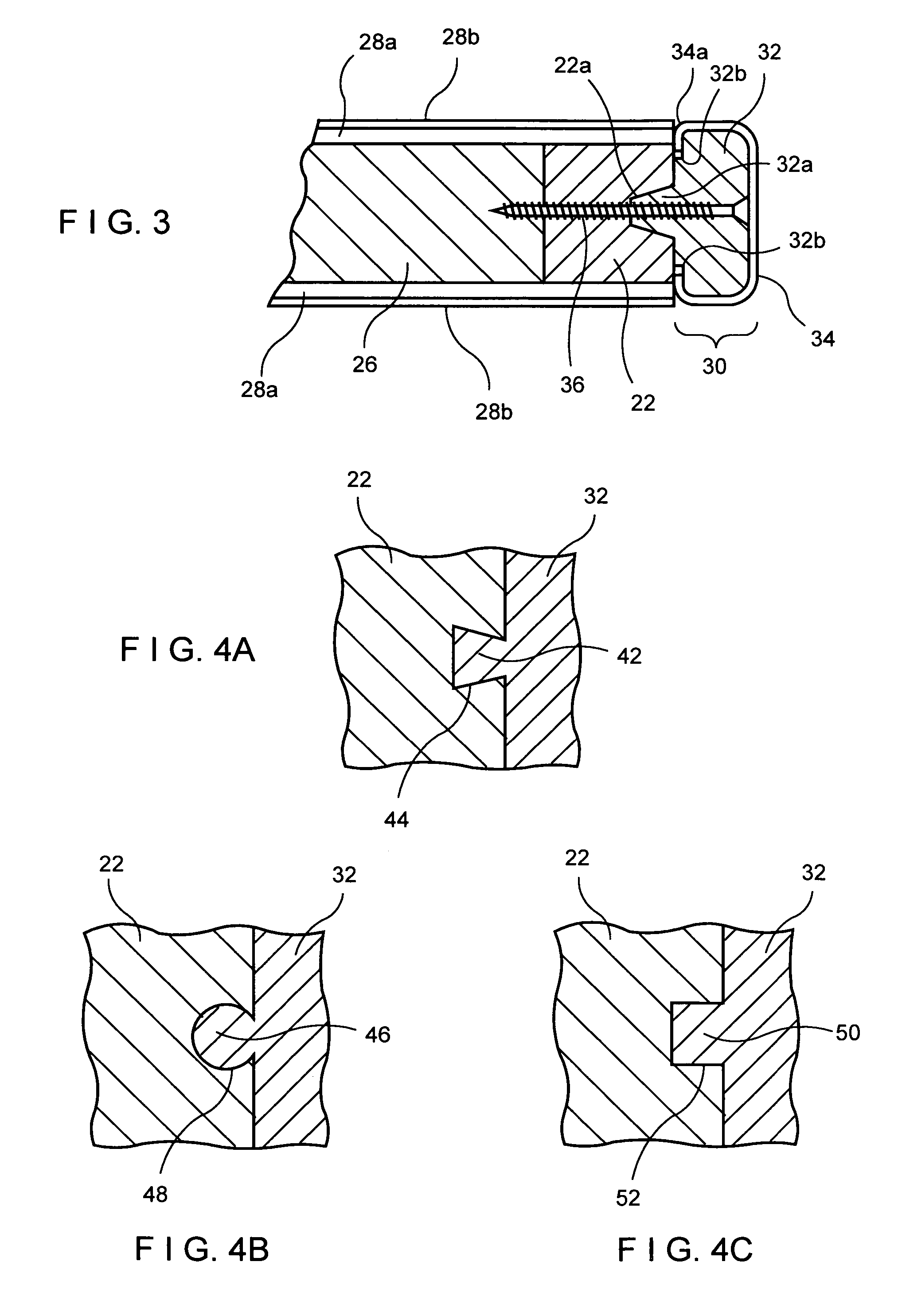
[0022] Turning now to the drawings, in particular FIGS. 1, 2 and 3, a door of the type commonly used in health care facilities and the like, but incorporating the present invention, is shown. Such a door 20 typically comprises vertical stiles 22 and top and bottom rails 24, surrounding a core 26. The stiles 22 and rails 24 preferably are made of hardwood and the core 26 of particle board, although other materials may be used to provide the necessary strength and rigidity.

[0023] Finish panels 28 cover the particle board core, top and bottom rails and stiles on both sides to provide strength, impact resistance and aesthetic appeal. As seen best in FIG. 3, the panels 28 may comprise a hardboard layer 28a covered by a decorative plastic cladding 28b such as of ACROVYN®, a vinyl acrylic plastic manufactured by Construction Specialties, Inc., Lebanon, N.J. The layers 26, 28a and b are laminated together to form a 5-ply construction. Doors of the type illustrated are manufactured, for exa...


PUM


Abstract

A door is constructed with a separate member joined to the door edge by a tongue-and-groove coupling and screws so as to be readily removable and replaceable. The separate member sustains the impacts imparted to the door by carts or wagons pushed past the door and can be readily replaced when damaged, thus avoiding replacement of the entire door. A flexible cover snaps over the outer surface of the separate member to add impact resistance and aesthetic appeal. Intumescent strips may be inserted inside or outside of the cover to enhance sealing between the door, and at the adjacent door or door frame, thereby improving the fire resistance rating of the door. Accent strips or reveals of contrasting or complementary colors may be incorporated to add to the aesthetic appeal of the door. The door construction is of particular utility in schools, health care facilities and other institutions.

Description

FIELD OF THE INVENTION [0001] The present invention relates generally to door constructions and more particularly, to replaceable door edge arrangements. BACKGROUND OF THE INVENTION [0002] One popular form of vertically hung doors typically comprises a wooden frame defining outer dimensions of the door, panels of sheet material, such as plywood, plastic or metal covering the frame or both sides, and a core within the frame, which may be solid or hollow. [0003] In certain high traffic environments, for example, schools, hospitals and other types of health care institutions, doors are often subjected to impacts from carts, wagons, dollies, etc. which take their toll on the doors, particularly along their free edges and the hinged edges. Nicks, gouges and cracks produced along door edges by such impacts compromise a door's ability to effect a secure closure, which is particularly important where the door serves as a fire barrier as well as a closure, and mar its aesthetic appearance. [...

Claims


Application Information

Patent Timeline
IPC IPC(8): E06B3/88E06B5/16
CPCE06B5/164E06B3/88
Inventor BARTLETT, GARY F.DUCKHAM, WENDY
Owner CONSTR SPECIALTIES
Learn More