
Low power shared link arbitration

a low-power shared link and arbitration technology, applied in the field of interconnection, can solve the problems of reducing the battery life of hand-held devices, requiring more rechargeable lines, and affecting the operation of the hand-held devi

Active Publication Date: 2005-04-07
META PLATFORMS TECH LLC
View PDF41 Cites 23 Cited by
  • Summary
  • Abstract
  • Description
  • Claims
  • Application Information

AI Technical Summary

Benefits of technology

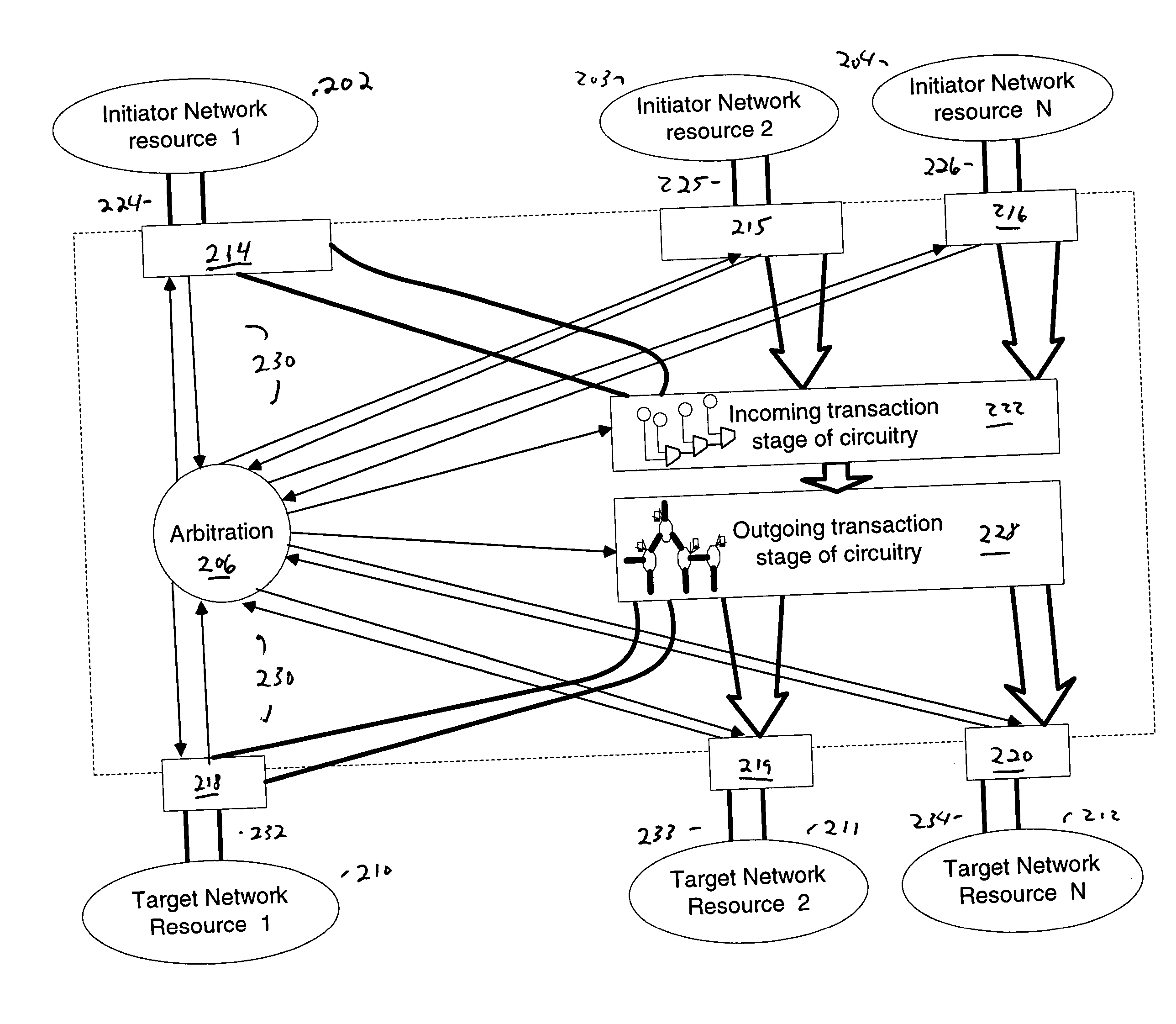
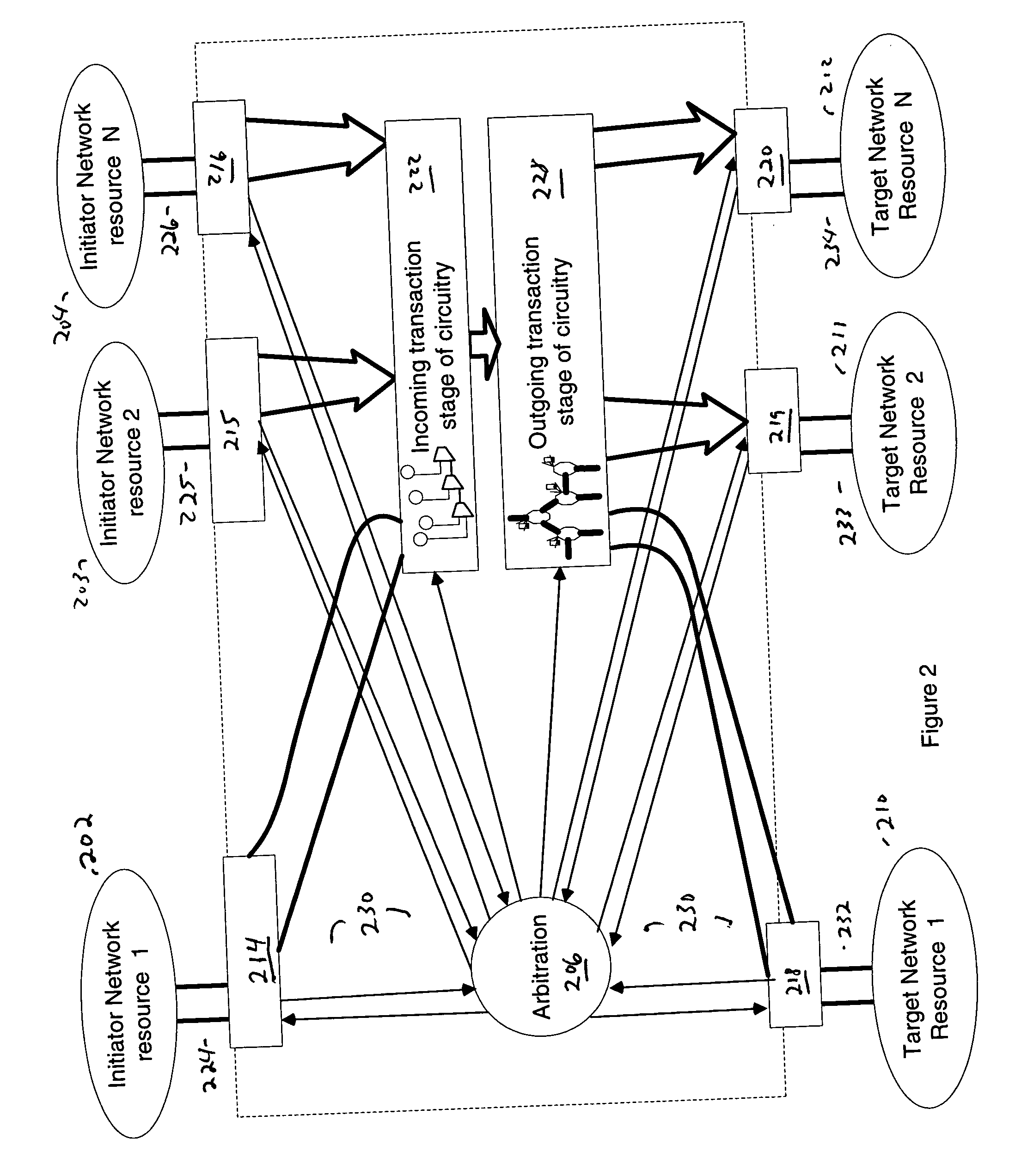
[0008] Various methods and apparatuses are described in which an interconnect couples to a plurality of initiator network resources and a plurality of target network resources. The interconnect may include a first stage of circuitry, a second stage of circuitry, and an arbitration controller. The first stage of circuitry receives incoming transactions from the plurality of initiator network resources. The second stage of circuitry passes outgoing transactions to the plurality of target network resources connecting to the interco...

Problems solved by technology

First, the conductive pathways must consume power to charge up from a low voltage state to a high voltage state.
Next, the conductive pathways adjacent to the conductive pathways transitioning from a high voltage state to a low voltage state may incur current leakage flow through the capacitance between the neighboring lines.
A small amount of leakage current flows out from the adjacent lines causing those lines to have to be recharged more often to replace the leaked charge.
The more often those conductive pathways have to be recharged, the more power is consumed, and that means a lower battery life for hand held devices.
This type of bus control mechanism wastes power.
Further, some system on chip designs are beginning to suffer potential performance problems because of the physical distance traveled on the chip for a fully combinational initiation of a request and payload transmission occurring in the same cycle.
The worst case physical distance needed to travel by the electrons across the chip can limit how fast the clock speed a particular chip may operate at.

Method used


Image

  • Low power shared link arbitration
  • Low power shared link arbitration
  • Low power shared link arbitration

Examples


Embodiment Construction

[0016] In the following description, numerous specific details are set forth, such as examples of specific data signals, named components, connections, types of network resources, etc., in order to provide a thorough understanding of the present invention. It will be apparent, however, to one of ordinary skill in the art that the present invention may be practiced without these specific details. In other instances, well known components or methods have not been described in detail but rather in a block diagram in order to avoid unnecessarily obscuring the present invention. Further specific numeric references such as first initiating network resource, may be made. However, the specific numeric reference should not be interpreted as a literal sequential order but rather interpreted that the first initiating network resource is different than a second initiating network resource. Thus, the specific details set forth are merely exemplary. The specific details may be varied from and sti...


PUM


Abstract

Various methods and apparatuses are described in which an interconnect couples to a plurality of initiator network resources and a plurality of target network resources. The interconnect may include a first stage of circuitry, a second stage of circuitry, and an arbitration controller. The first stage of circuitry receives incoming transactions from the plurality of initiator network resources. The second stage of circuitry passes outgoing transactions to the plurality of target network resources connecting to the interconnect. The arbitration controller arbitrates transactions from the plurality of initiator network resources destined to one or more of the target network resources. The target network resources supply their availability to service a transaction to the arbitration controller. The arbitration controller implements an arbitration policy that filters out transactions from the arbitration process those transactions from initiator network resources destine to target network resources that are currently not available to service a transaction.

Description

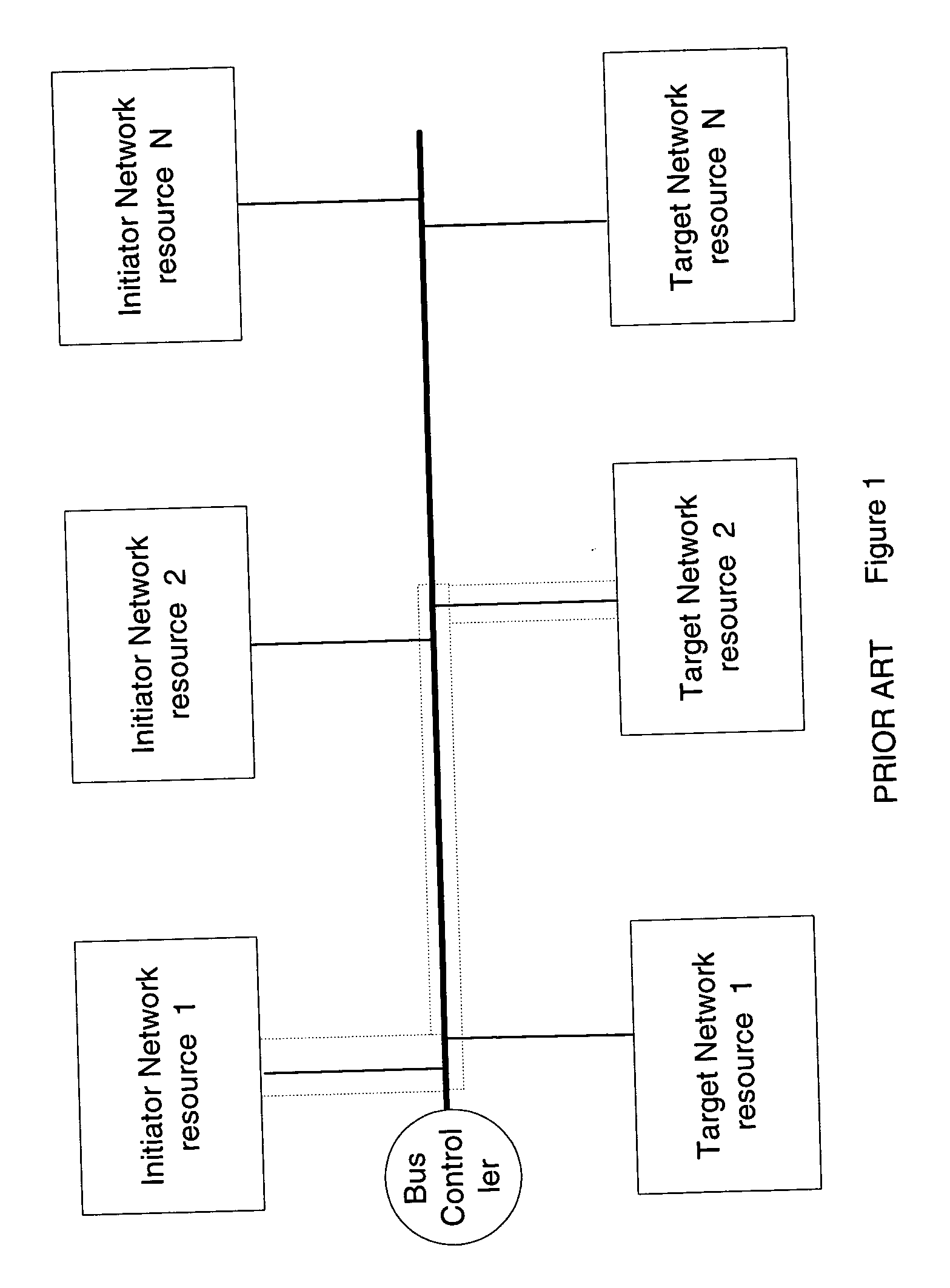
FIELD OF THE INVENTION [0001] Embodiments of the invention generally relate to an interconnect in a networked environment. More particularly, an aspect of an embodiment of the invention relates to interconnect having an arbitration controller to implement an arbitration policy that minimizes power consumption. BACKGROUND OF THE INVENTION [0002]FIG. 1 illustrates a block diagram of a prior art bus mechanism to establish a connection path between initiator network resources to target network resources across a bus. The network may consist of various network resources that may initiate requests such as initiating network resources 1 through N, where N indicates any number. The network may also contain target network resources, which will service the requests of the initiating network resources. The target network resource may contain target network resources such as target network resources 1 through N. The system may contain a bus controller for controlling the transactions between th...

Claims


Application Information

Patent Timeline
IPC IPC(8): G06F13/364H04L12/403
CPCG06F13/364H04L12/40032Y02B60/1228H04L12/4625H04L12/403Y02D10/00G06F13/36G06F13/14G06F13/00
Inventor WEBER, WOLF-DIETRICHWINGARD, DREW E.
Owner META PLATFORMS TECH LLC
Learn More