
Mitral valve prosthesis

a technology for mitral valves and prostheses, applied in the field of mitral valve prosthesis, can solve the problems of loss of continuity, and achieve the effect of facilitating sewing of the mitral valve prosthesis

Inactive Publication Date: 2005-04-07
THE UNIV COURT OF THE UNIV OF GLASGOW
View PDF17 Cites 766 Cited by
  • Summary
  • Abstract
  • Description
  • Claims
  • Application Information

AI Technical Summary

Benefits of technology

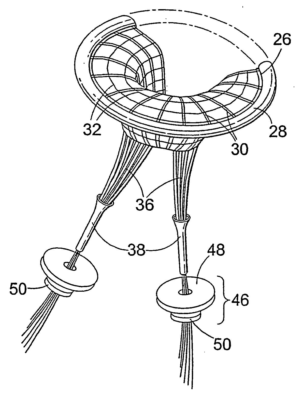
A significant advantage of the present invention, in use, lies in the maintenance of continuity between the papillary muscles and the mitral annulus by the provision of the at least one continuity member, such that left ventricular function is maintained. Furthermore, continuity may be optimised according to the dimensions of each individual heart due to the adjustability of the continuity member. Loss of such continuity is inherent in the process of removal of the diseased mitral valve and subsequent replacement using a conventional prosthetic heart valve.
, in use, lies in the maintenance of continuity between the papillary muscles and the mitral annulus by the provision of the at least one continuity member, such that left ventricular function is maintained. Furthermore, continuity may be optimised according to the dimensions of each individual heart due to the adjustability of the continuity member. Loss of such continuity is inherent in the process of removal of the diseased mitral valve and subsequent replacement using a conventional prosthetic heart valve.
According to a second aspect of the present invention there is provided a heart valve prosthesis comprising: a support adapted to be coupled to the mitral annulus; first and second valve elements coupled to the support and moveable between an open position and a closed position, the elements defining curved coapting surfaces, each surface having at least two points of inflection; and at least one continuity member having one end coupled to said support and the other end adapted for coupling to papillary muscle.
This second aspect of the present invention provides a form which allows flow of blood through the open valve prosthesis, the form of the valve elements providing an open flow area comparable to the open flow area of the natural valve, despite the use of relatively stiff synthetic material to form the valve elements.
Preferably, the support has a ring-like or annular structure. The support may comprise a semi-rigid structure, and may comprise a suitable metal.
Conveniently, the support is incorporated into a fabric sewing ring. Preferably, said fabric sewing ring is formed of polytetrafluoroethylene or the like. Such a sewing ring facilitates sewing of the mitral valve prosthesis into the mitral orifice of the heart once the diseased or defective valve has been removed.

Problems solved by technology

Loss of such continuity is inherent in the process of removal of the diseased mitral valve and subsequent replacement using a conventional prosthetic heart valve.

Method used


Image

  • Mitral valve prosthesis
  • Mitral valve prosthesis
  • Mitral valve prosthesis

Examples


Embodiment Construction

Mathematical Representations of Valve Designs in Closed Position.

The mathematically modelled mitral valve designs are based on the physical model of a mitral valve prosthesis in accordance with an embodiment of the invention moulded out of Woods metal. The designs are all symmetrical about a centre line, so it is sufficient to construct one half of the posterior and anterior leaflets, and then mirror these to complete the designs. For example, the posterior half-leaflet (of FIG. 11) is constructed as follows. The portion of the annulus perimeter curve is drawn first, from the centre-line position to the commisure where it meets the anterior region. The centre-line curve then is drawn at right angles from the annulus curve centre point. Finally, a 3D curve is drawn to connect the centre-line curve to the commissure. This 3D curve is a half-section of the free edge of the leaflet and is constructed by means of three 2D boundary curves Using these three boundary curves, it is possib...


PUM


Abstract

The present invention relates to a mitral valve prosthesis comprising flexible leaflet-like elements with curved coapting surfaces and means for maintaining continuity of the valve when inserted into the mitral annulus, which mimics the continuity between the papillary muscles, the chordae tendineae, the mitral valve leaflets and the mitral annulus of a natural valve. The present invention also relates to a method of fitting such a prosthesis to heart of a patient.

Description

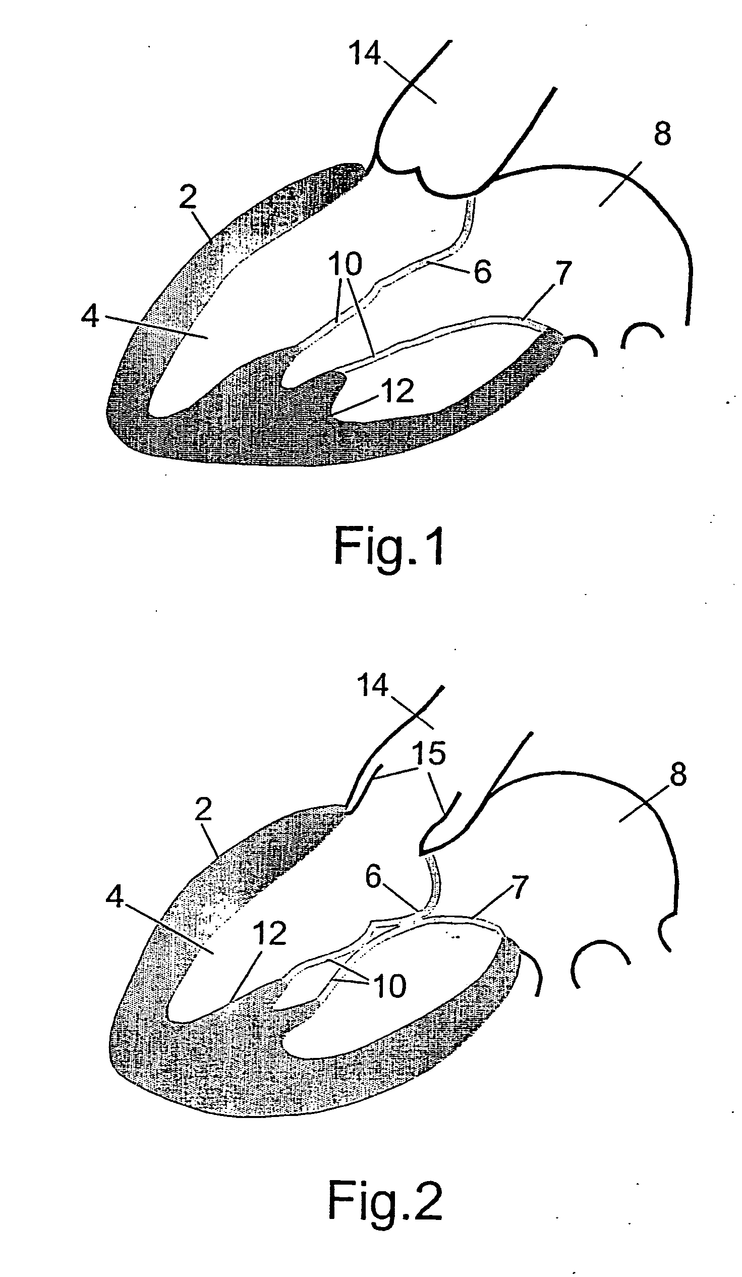
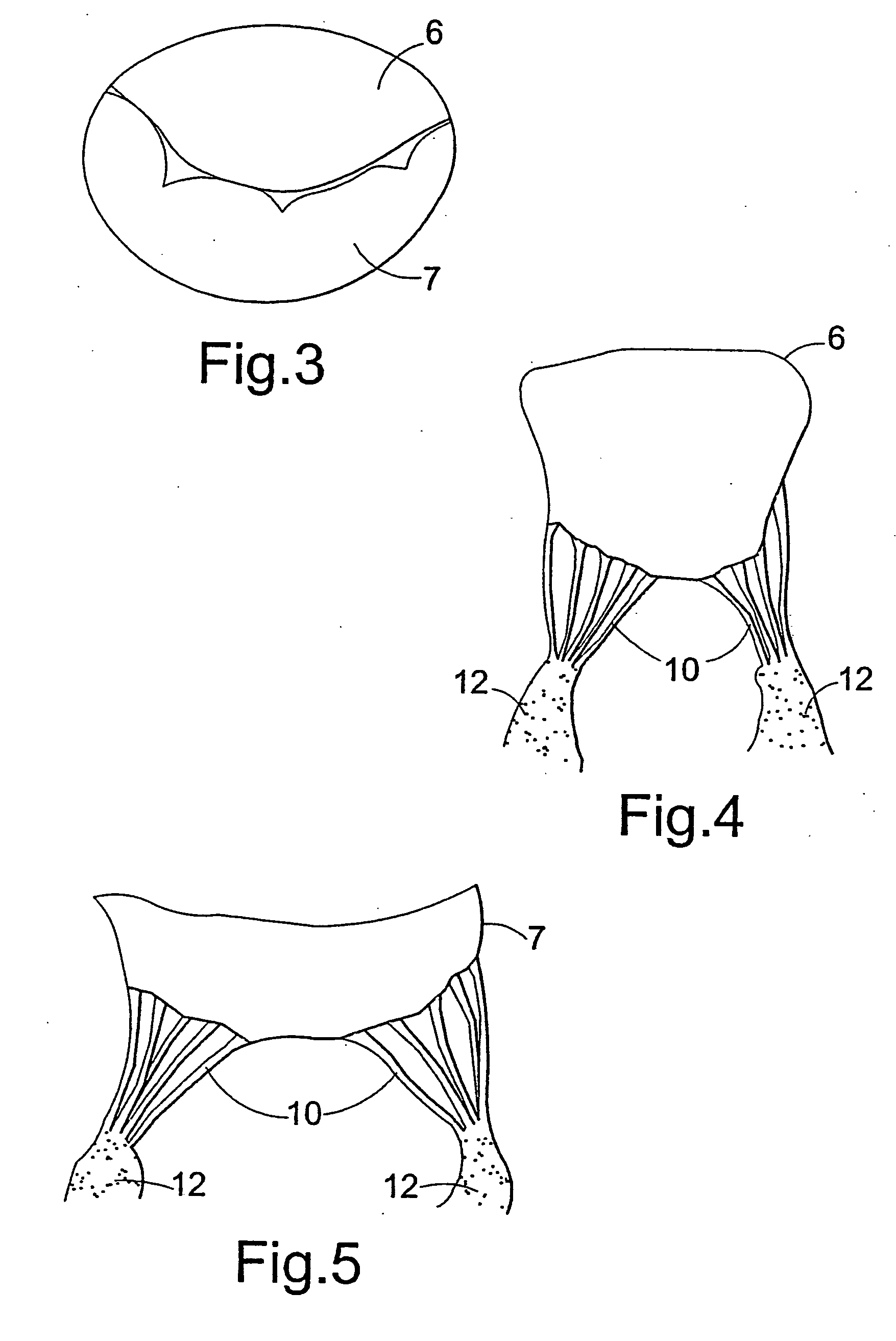
FIELD OF THE INVENTION This invention relates to a mitral valve prosthesis, and to a method of fitting such a prosthesis to the heart of a patient. BACKGROUND OF THE INVENTION The mitral valve controls blood flow at the orifice between the left atrium (a receiving chamber for blood coming from the lungs) and the left ventricle (the high pressure muscular pumping chamber of the heart), which ejects blood into the aorta (the main artery which distributes blood around the body through its branches). When the left ventricular muscle relaxes, the cavity of the left ventricle expands to receive blood through the open mitral valve (FIG. 1); when the left ventricle 4 muscle contracts, the mitral valve leaflets 6, 7 close and the blood in the left ventricle 4 is expelled through the open aortic valve 15 into the aorta 14 (FIG. 2). The mitral valve has the function of preventing reverse blood flow back into the left atrium 8 when the left ventricle is contracting. The mitral valve has two ...

Claims


Application Information

Patent Timeline
Patent Type & Authority Applications(United States)
IPC IPC(8): A61F2/24
CPCA61F2/2457A61F2/2412
Inventor WHEATLEY, DAVID JOHN
Owner THE UNIV COURT OF THE UNIV OF GLASGOW
Learn More