
Device and method for preparative electrophoresis

a technology of electrophoresis and electrophoresis gel, which is applied in the direction of fluid pressure measurement, liquid/fluent solid measurement, peptide measurement, etc., can solve the problems of only a low degree of mechanical and chemical stability, unable to scale up within narrow limits, and unable to achieve non-negligible pressure-induced transmembrane flow

Inactive Publication Date: 2005-04-07
BAYER INTELLECTUAL PROPERTY GMBH
View PDF10 Cites 16 Cited by
  • Summary
  • Abstract
  • Description
  • Claims
  • Application Information

AI Technical Summary

Benefits of technology

It has now been found that the electroosmotic flow in the membranes employed, and the volume changes resulting therefrom, can be offset by superimposing a regulated hydrostatic pressure.
Preference is given to a a pressure difference between the diluate space and the concentrate space which is adjusted such that any liquid flow through the separation membrane which separates the concentrate space and the diluate space from each other is essentially prevented.
Preference is also given to an embodiment in which the conductivity of the diluate solution is lowered during the separation.

Problems solved by technology

Although this technique leads to good selectivities on a laboratory scale, scaling-up is only possible within narrow limits.
The main problem is considered to be the heating of the solution in the electrical field and the dispersion phenomena, such as heat convection, resulting from this.
However, these materials suffer from a number of disadvantages: they do not exhibit any selectivity for the substances to be separated (U.S. Pat. No. 3,989,613, U.S. Pat. No. 4,043,895) and, in addition to this, frequently exhibit only a low degree of mechanical and chemical stability.
Moreover, they are susceptible to non-negligible pressure-induced transmembrane flows at pressure differences of less than 1 kPa.
Pressure differences, which can vary temporarily or locally, between individual compartments consequently lead to backmixing and to a decrease in separation efficiency.
However, very low productivity is observed in practice when using ultrafiltration membranes.
While productivity decreases in the first case, the second case results in a decrease in separation efficiency since proteins of low mobility, which should remain in the diluate, can be transported convectively through the membrane.
It is consequently not possible to equalize liquid flows through the separation membranes by equalizing hydrostatic pressure differences in the module, as described, for example, in U.S. Pat. No. 4,043,895.
However, gel membranes suffer from a number of disadvantages as compared with porous membranes:
This leads to high energy input and consequently to the evolution of a great deal of heat in the module.
Gels such polyacrylamide possess poor pH stability and cannot therefore be cleaned like conventional ultrafiltration and microfiltration membranes.
This results in very high costs for module replacement since cleaning when handling proteins is essential.
On the one hand, the use of ultrafiltration and microfiltration membranes for membrane electrophoresis has thus far been limited by the electroosmotic effect.
On the other hand, while gel membranes can be used, with the above-mentioned disadvantages, scaling-up fails because of the membrane costs and energy input being too high.
Because of the electroosmotic flow which develops in porous membranes, use of these membranes on an industrial scale (>0.5 kg / h), for example, has not previously been possible.

Method used


Image

  • Device and method for preparative electrophoresis
  • Device and method for preparative electrophoresis
  • Device and method for preparative electrophoresis

Examples


example 1

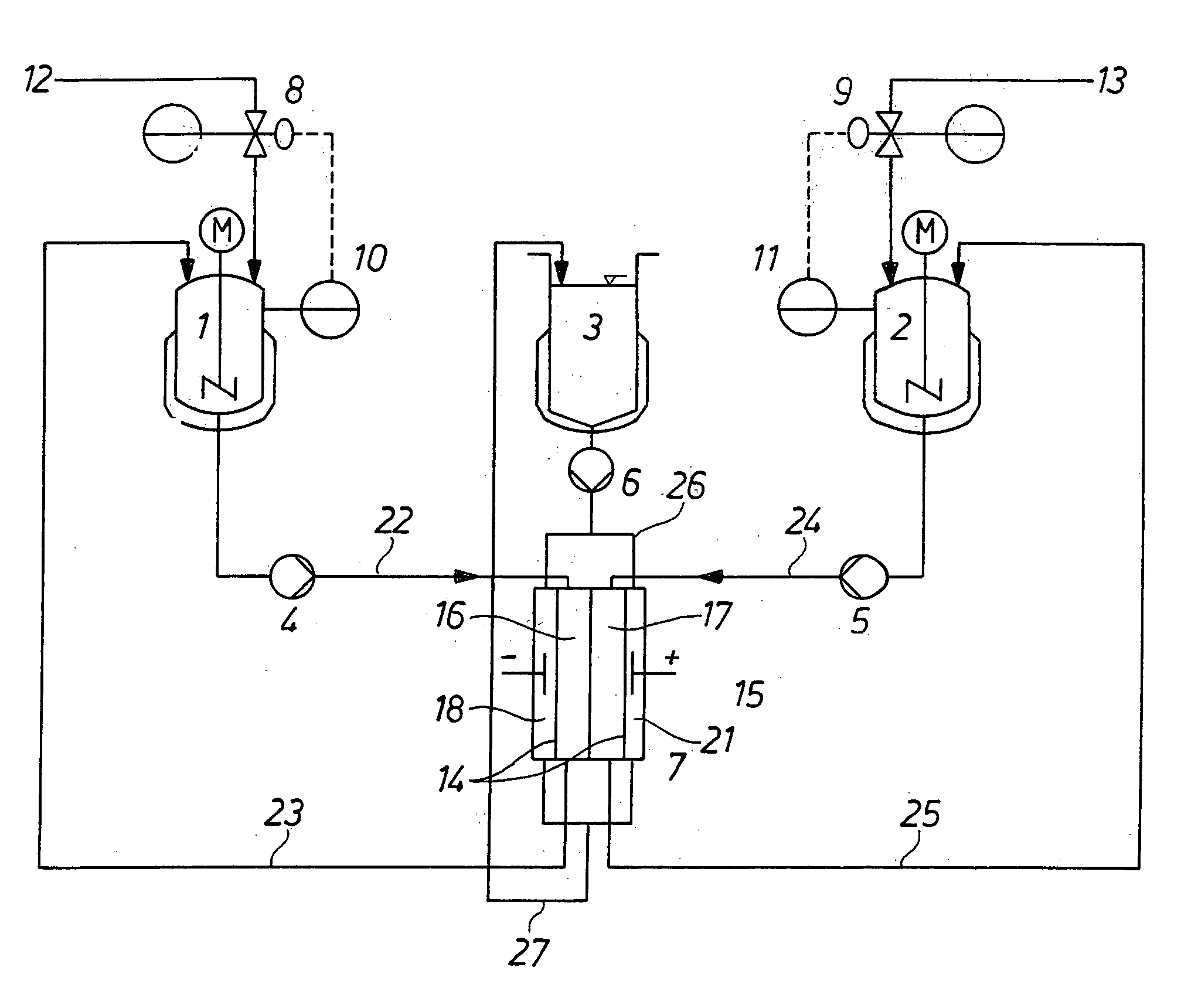
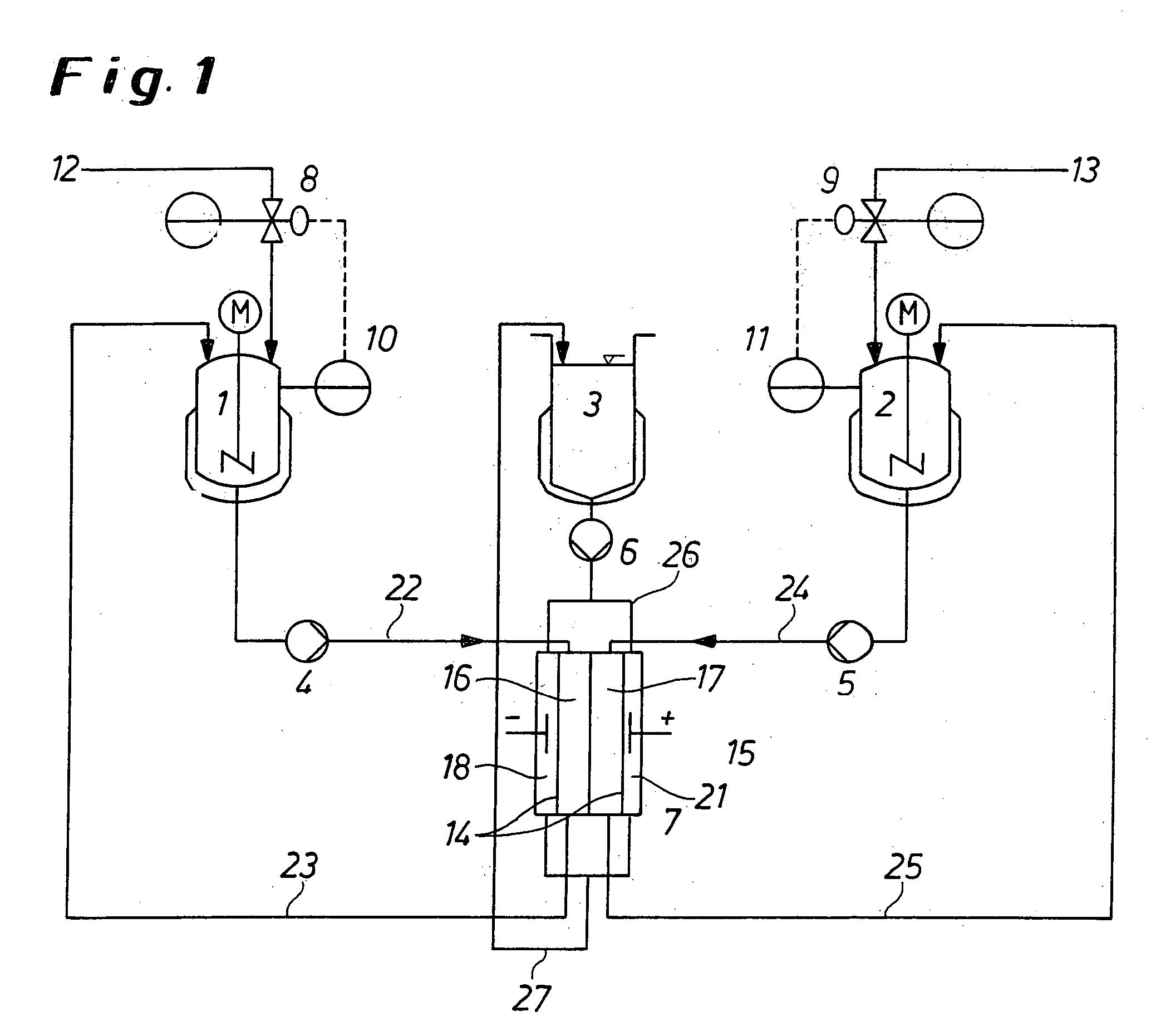
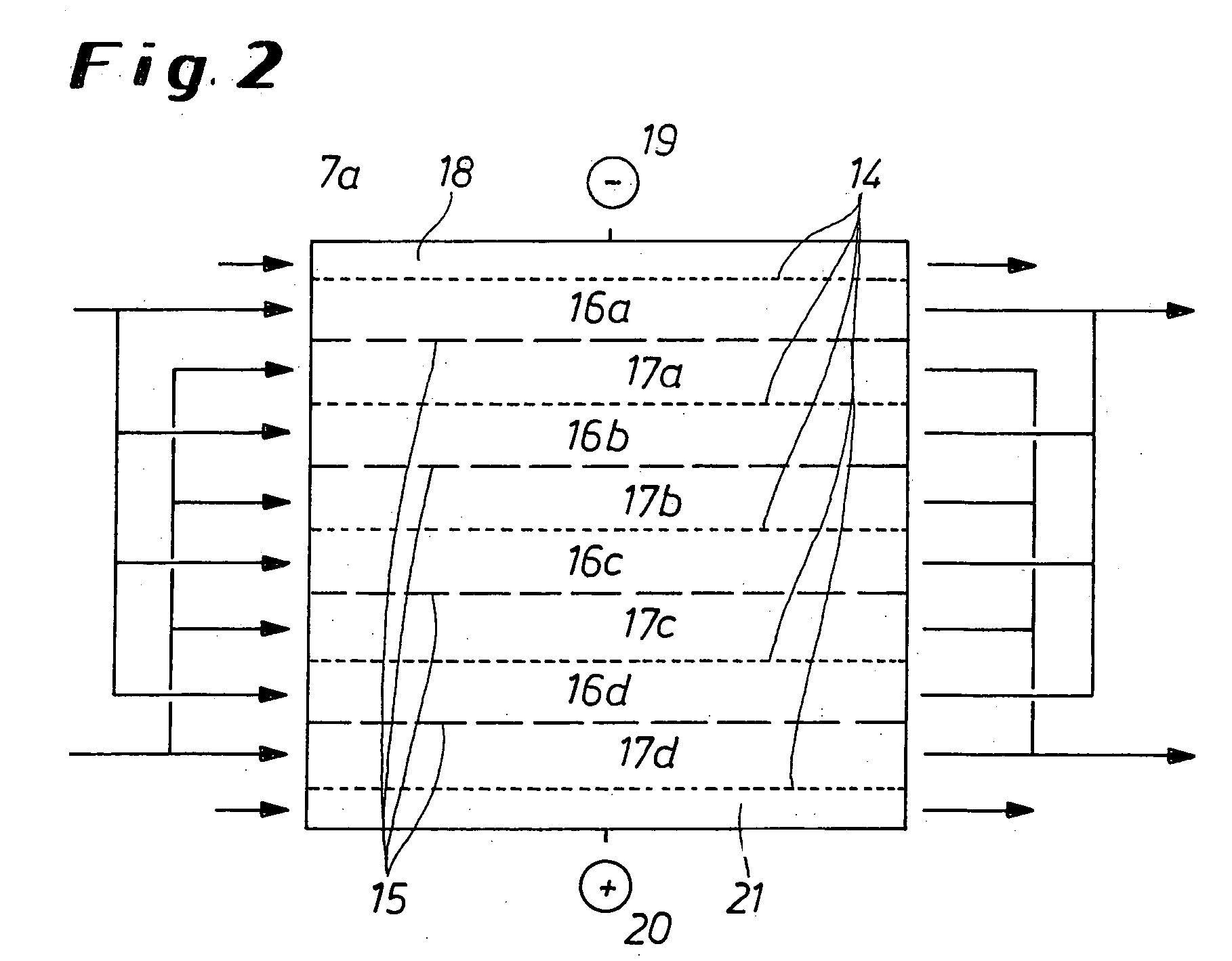
The unit shown in FIG. 1 and the module 7a sketched in FIG. 2 were used for separating human serum albumin (HSA) from human immunoglobulin G (IgG). Module 7a was a modified electrodialysis module ED 136 from FuMA-Tech GmbH) having an effective membrane area of 36 cm2 per membrane layer.

A HEPES(2-[4-(2-hydroxyethyl)-1-piperainyl]ethane sulphonic acid)imidazole buffer was used (approx. 40 mM HEPES / 15 mM imidazole, pH 7). The recipient vessels for concentrate solution 2 and electrode rinsing solution 3 were in each case filled with 1,000 mL of a buffer solution. The diluate recipient vessel was filled with 400 mL of buffer in which HSA and IgG were dissolved at concentrations of 38 g / L and 4.5 g / L, respectively.

Restriction membranes 14 having a nominal cutoff point of 10 kDa and separation membranes 15 having a nominal cutoff point of 300 kDa were assembled, using standard spacers (from FuMA-Tech GmbH), into a quadruple stack. The membranes which were used were SARTORIUS® PES poly...

example 2

The unit shown in FIG. 1 and the module 7a sketched in FIG. 2 were used for separating human serum albumin from haemoglobin. The module 7a was a modified electrodialysis module as in Example 1 having an effective membrane area of 36 cm2 per membrane layer.

50 millimolar MES / hisitidine buffer was used (approx. 15 mM MES / 35 mM histidine, pH 6.5). The recipient vessels for concentrate solution 2 and electrode rinsing solution 3 were filled with 1 L and 800 mL of buffer solution, respectively. The diluate recipient vessel 1 contained the two proteins dissolved in buffer at mass concentration of 4.5 g / L of human serum albumin and 0.85 g / L of haemoglobin. The volume of the diluate liquid was 400 mL and was kept constant during the experiment by means of pressure superposition.

Restriction membranes 14 having a nominal cutoff point of 10 kDa and separation membranes 15 having a nominal cutoff point of 300 kDa were assembled, using standard spacers as in Example 1, into a quadruple stack...


PUM

PropertyMeasurementUnit
Pore sizeaaaaaaaaaa
Pressureaaaaaaaaaa
Electrical conductivityaaaaaaaaaa

Abstract

Method and appliance for carrying out membrane electrophoresis using microfiltration or ultrafiltration membranes, wherein the electroosmotic flow which develops in the membrane pores is reduced or offset by pressure superposition. The appliance for the membrane electrophoresis comprises at least an at least quadrupartite separation chamber (7), having at least one diluate space (16) and one concentrate space (17) and also a cathode space (18) and an anode space (21) having electrodes as anode (19) and cathode (20), with the individual spaces (16, 17, 18, 21) being separated from each other by ultrafiltration or microfiltration membranes (14, 15); feed lines (22) and discharge lines (23) for the diluate, feed lines (24) and discharge lines (25) for the concentrate, optionally feed lines (26) and discharge-lines (27) for the electrode rinsing solution, and also a device (8; 10) or (9; 11) for pressure regulation by means of which a pressure difference, in particular of at least 3 kPa, can be generated between the diluate space (16) and the concentrate space (17).

Description

The invention relates to a method and an appliance for performing membrane electrophoresis using microfiltration or ultrafiltration membranes. In the method, the electroosmotic flow which develops in the membrane pores is reduced or compensated for by means of pressure superposition. BACKGROUND OF THE INVENTION The possibility of using electrophoresis as a preparative separation technique has been investigated since the nineteen fifties. In continuous free-flow electrophoresis, a solution flows into an electrophoresis chamber and is separated in the electrical field between two electrodes. On leaving the electrophoresis module, the liquid flow is divided into a large number of fractions which contain the substances to be separated at different concentrations. Although this technique leads to good selectivities on a laboratory scale, scaling-up is only possible within narrow limits. The main problem is considered to be the heating of the solution in the electrical field and the di...

Claims


Application Information

Patent Timeline
IPC IPC(8): B01D57/02B01D61/42B01D61/50B01D61/54B01D61/58C07K1/26
CPCB01D57/02B01D61/025B01D61/027C07K1/26B01D61/147B01D61/425B01D61/58B01D61/145
Inventor DUDZIAK, GREGORNICKEL, ANDREASMUTTER, MARTINABAUMARTH, KERSTIN
Owner BAYER INTELLECTUAL PROPERTY GMBH
Learn More