
Solid state dye-sensitized solar cell employing composite polymer electrolyte

a solar cell and composite polymer technology, applied in the direction of light-sensitive devices, capacitors, electrolytic capacitors, etc., can solve the problems of inability to commercialize, the use of solar cells in long-term stable and commercial applications is very unsuitable, and the electrolyte solution is likely to volatilize, etc., to achieve high energy conversion efficiency

Inactive Publication Date: 2005-04-07
KOREA INST OF SCI & TECH
View PDF9 Cites 41 Cited by
  • Summary
  • Abstract
  • Description
  • Claims
  • Application Information

AI Technical Summary

Benefits of technology

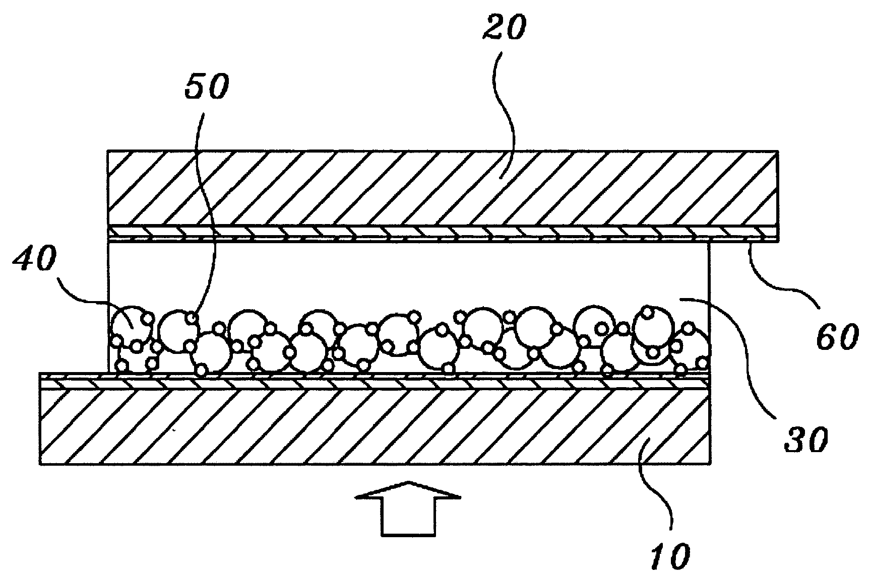
[0011] Therefore, the present invention has been made keeping in mind the above disadvantages occurring in the prior arts, and an object of the present invention is to provide a dye-sensitized solar cell, which assures high energy conversion efficiency without an electrolyte leak.

Problems solved by technology

However, when an external temperature of the dye-sensitized solar cell, including the liquid electrolyte produced using the organic solvent, is increased due to sunlight, the solvent of the electrolyte is likely to become volatilized.
Accordingly, use of the solar cell in long-term stable and commercial applications is very unsuitable because of a solvent leak.
However, the solar cell employing the polymer electrolyte is disadvantageous in that its commercialization is impossible because of poor energy conversion efficiency.
Other disadvantages are that its ionic conductivity is poorer than that of the solar cell employing the liquid electrolyte (wet solar cell), when a molecular chain of the polymer is long it is difficult to penetrate the electrolyte into pores between the semiconductor nanoparticles, and current density of the solar cell is significantly reduced if the polymer electrolyte insufficiently wraps the semiconductor nanoparticles or is not connected to the semiconductor nanoparticles without a short circuit.

Method used


Image

  • Solid state dye-sensitized solar cell employing composite polymer electrolyte
  • Solid state dye-sensitized solar cell employing composite polymer electrolyte
  • Solid state dye-sensitized solar cell employing composite polymer electrolyte

Examples


example 1

First Production of a Dye-Sensitized Solar Cell (Single Layer Coating Method)

[0059] Production of a Polymer Electrolyte

[0060] Polyethylene oxide (PEO, Rg=420 Å, Tg=−67° C., Tm=66° C., Aldrich Co.) and polypropylene glycol (PPG, Rg=10 Å, Tg=−73° C., Tm=66° C., Aldrich Co.) in a predetermined ratio (PEO / PPG=4 / 6, weight ratio) were dissolved in 9.5 g of acetonitrile to produce a homogeneous and transparent polymer solution (polymer concentration of 5 wt %). Sodium iodide (NaI, Aldrich Co.) was added to the polymer solution so that a molar ratio of [—O—]:[NaI] was 20:1 ([—O—] means the number of moles of ether groups contained in all polymer chains). An amount of added iodine (I2) was fixed to 10 wt % based on sodium iodide. Thereby, the polymer electrolyte was created.

[0061] Production of the Dye-Sensitized Solar Cell

[0062] After the Polymer Electrolyte Having a Polymer concentration of 5 wt % was cast on a photoelectrode, onto which Ru(dcbpy)2(NCS)2 (Ru 535, Solaronix, Switzerland...

example 2

Second Production of the Dye-Sensitized Solar Cell (Multilayer Coating Method)

[0063] Production of a Polymer Electrolyte

[0064] The polymer electrolyte was produced according to the same procedure as example 1.

[0065] Production of the Dye-Sensitized Solar Cell

[0066] After the polymer electrolyte with a polymer concentration of 5 wt % was cast on a photoelectrode, onto which Ru(dcbpy)2(NCS)2 (Ru 535, Solaronix, Switzerland), acting as an organic dye, was adsorbed, and onto a counter electrode, acetonitrile acting as a solvent was volatilized for 1 min. Next, the polymer electrolyte having a polymer concentration of 5 wt % was concentrated to produce a highly concentrated polymer electrolyte having a polymer concentration of 50 wt %. Subsequently, the highly concentrated polymer electrolyte was cast again on the photoelectrode, and the counter electrode was laminated on the resulting photoelectrode. As in example 1, the dye-sensitized solar cell was interposed between two glass sub...

experimental example 1

[0067] Polyethylene oxide (PEO, Rg=420 Å, Tg=−67° C., Tm=66° C., Aldrich Co.) and polypropylene glycol (PPG, Rg=10 Å, Tg=−73° C., Tm=66° C., Aldrich Co.) in a predetermined ratio were dissolved in 9.5 g of acetonitrile to produce a homogeneous and transparent polymer solution (polymer concentration of 5 wt %). Sodium iodide (NaI, Aldrich Co.) was added to the polymer solution so that a molar ratio of [—O—]:[NaI] was 20:1. An amount of added iodine (I2) was fixed to 10 wt % based on sodium iodide. Thereby, the polymer electrolyte was created.

[0068] The polymer electrolyte solution was coated on a photoelectrode, including a titanium oxide layer, onto which an organic dye was adsorbed, and onto a counter electrode, on which platinum is coated, according to a multilayer coating method, adopting a two-stage coating process, to produce a dye-sensitized solar cell (sample 1). A solvent was completely removed from the solar cell using a vacuum oven for 5 days or more, and an open-circuit ...


PUM


Abstract

Disclosed is a solid state dye-sensitized solar cell employing a composite polymer electrolyte, which includes a photoelectrode, a counter electrode, and an electrolyte interposed between the photoelectrode and counter electrode. The electrolyte includes at least one of a middle molecular substance, a polymer mixture, and inorganic nanoparticles, and a redox derivative. The dye-sensitized solar cell reduces crystallinity of the polymer electrolyte to significantly increase ionic conductivity, and enables the polymer electrolyte to smoothly permeate into a titanium oxide layer to improve mechanical properties, thereby significantly increasing energy conversion efficiency. Accordingly, the dye-sensitized solar cell assures high energy conversion efficiency without an electrolyte leak, and thus, it can be stably and practically used for a long time.

Description

BACKGROUND OF THE INVENTION [0001] 1. Field of the Invention [0002] The present invention relates, in general, to a solid state dye-sensitized solar cell employing a composite polymer electrolyte and, more particularly, to a solid state dye-sensitized solar cell employing a composite polymer electrolyte, which includes a photoelectrode, a counter electrode, and an electrolyte sandwiched between the photoelectrode and counter electrode, and in which the composite polymer electrolyte includes one selected from the group consisting of middle molecular substances, or the mixtures of the middle molecular substances and polymer, and the mixtures of the middle molecular substances and inorganic nanoparticles, and redox couples. Here the photoelectrode includes transparent conducting layer, semi-conducting nanoporous layer and dye photosensitizer. [0003] 2. Description of the Prior Art [0004] A solar cell, which is capable of generating electricity without emitting a pollutant, thereby prov...

Claims


Application Information

Patent Timeline
IPC IPC(8): H01G9/20H01L31/04H01L31/00H01M14/00
CPCH01G9/2009H01G9/2031H01G9/2022Y02E10/542H01G9/2059H01L31/04
Inventor KANG, MOON SUNGKIM, JONG HAKKIM, YOUNG JINWON, JONGOKKANG, YONG SOOKIM, HOON SIK
Owner KOREA INST OF SCI & TECH
Learn More