
Pinch valve element for plumbing fixture flush valve

Active Publication Date: 2005-03-31
SDB IP HLDG
View PDF6 Cites 6 Cited by
  • Summary
  • Abstract
  • Description
  • Claims
  • Application Information

AI Technical Summary

Benefits of technology

[0008] It is an object of the present invention to provide a valve replacement for a diaphragm valve that overcomes the deficiencies of the prior art. It is another object of the present invention to provide a valve replacement for a diaphragm valve that has a decreased failure rate and, therefore, an increased cost efficiency. It is a further object of the present invention to provide a valve replacement for a diaphragm valve that has a larger seal area, such that small debris cannot be trapped in the seal area and hold the valve open. It is a still further object of the present invention to provide a valve replacement for a diaphragm valve that has a decreased flush time with a high flow rate and velocity, thereby being more water efficient. It is yet another object of the present invention to provide a valve replacement for a diaphragm valve that is capable of resetting at low pressure, such as when a facility loses mainline pressure.

Problems solved by technology

For example, the relatively small seal area in the diaphragm can become clogged with debris, which causes the flush valve to remain open, resulting in constant water flow.
This small bleed hole is easily clogged, which can also result in the malfunction of the valve.
Therefore, a significant amount of water is wasted through the trap and sewer line during the sealing process.
The trip lever seal area can also be blocked with debris, which causes the valve to flow continuously.
Yet another drawback is that conventional diaphragm flush valves only work at water pressures greater than 35 psi, which is due to the difference in the diaphragm surface area and the diameter of the bleed hole.
Heretofore, however, the use of such a pinch valve as a replacement valve in the application of flush valves for plumbing fixtures has not been effective due to the different sealing arrangement bound in pinch valves in comparison to diaphragm valves.

Method used


Image

  • Pinch valve element for plumbing fixture flush valve
  • Pinch valve element for plumbing fixture flush valve
  • Pinch valve element for plumbing fixture flush valve

Examples


Embodiment Construction

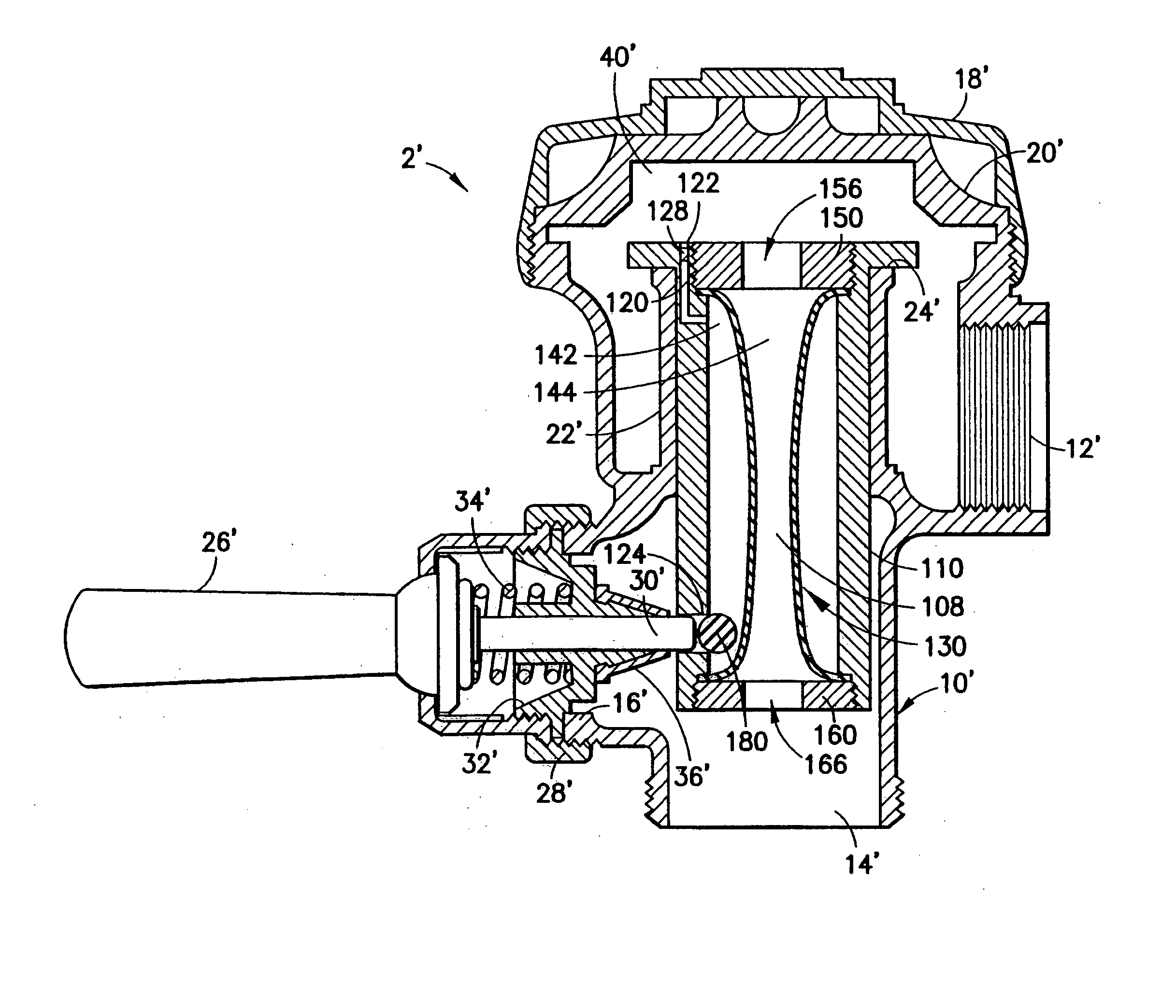
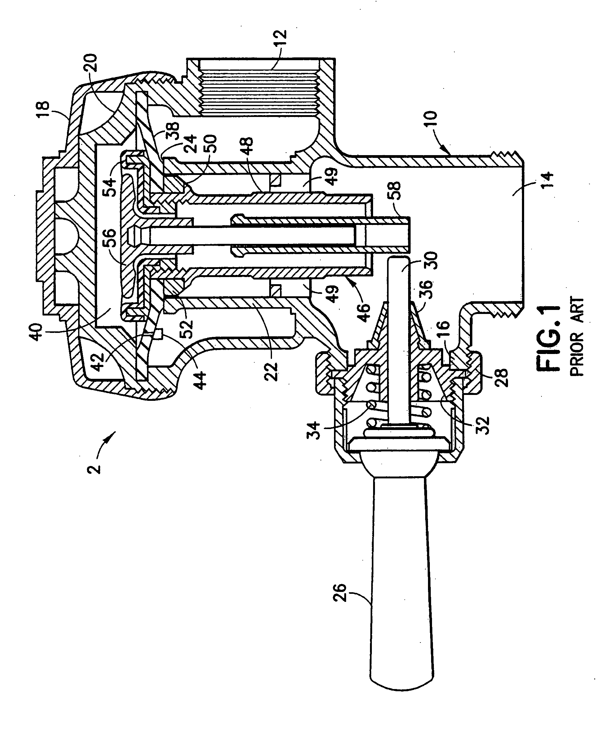
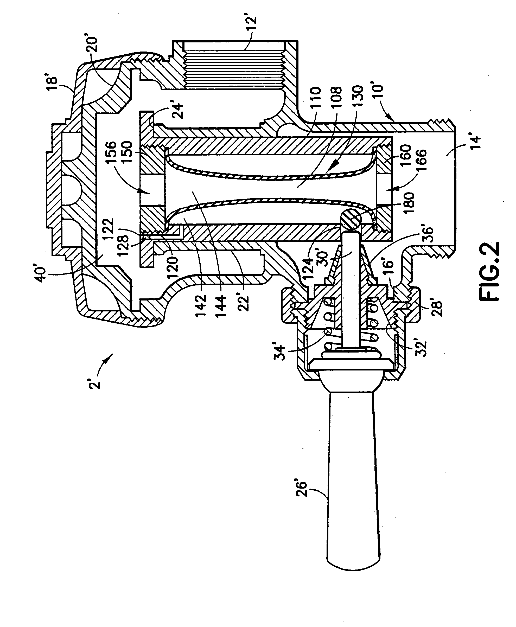
[0023] The present invention relates to flush valves, and in particular to an improved valve insert for use in such valves. The valve insert is particularly useful for replacement of a traditional diaphragm-type valve insert for flush valves. Such traditional diaphragm-type valves are shown in U.S. Pat. No. 4,327,891, as depicted in FIG. 1 herein. In such diaphragm-type flush valves, the flush valve 2 has a general hollow body 10 which includes an inlet connection 12, an outlet connection 15 and a handle coupling connection 16. The top of the valve body is closed by an outer cover 18 and an inner cover 20. The inlet portion of the valve is separated from the outlet portion by a central throat 22 which is attached to the inside walls of the valve body 10. A main valve seat 24 is formed on the top of the throat.

[0024] The valve is actuated by an operating handle 26 which is fastened to the valve body 10 by means of coupling nut 28. The handle is connected to a plunger 30 which extend...


PUM


Abstract

The present invention discloses a pinch valve for replacing a diaphragm valve in a plumbing fixture. The plumbing fixture includes an inlet chamber defining a fluid inlet and in fluid communication with an inside chamber defining a fluid outlet. The pinch valve includes a cartridge member with a fluid inlet opening, a fluid outlet opening and a cartridge chamber defined by a cartridge chamber wall and in fluid communication with the fluid inlet opening and the fluid outlet opening. A flexible sealing member is positioned at least partially within the cartridge chamber and includes a wall with an inner surface defining an inner chamber and an outer surface defining an outer chamber between the outer surface of the flexible sealing member wall and the cartridge chamber wall. The inlet chamber of the plumbing fixture is in fluid communication with the inner chamber and the outer chamber.

Description

BACKGROUND OF THE INVENTION [0001] 1. Field of the Invention [0002] The present invention relates generally to flush valves used in connection with plumbing fixtures, such as toilets, urinals and the like, and in particular, to a replacement for a diaphragm valve in such a plumbing fixture. [0003] 2. Description of Related Art [0004] Valves are used throughout many fluid transfer systems and in various applications, such as in the transfer and control of water conduit systems, and in particular in connection with plumbing fixtures in both residential and commercial settings. For example, flush valves are typically used for control and operation of toilets, urinals and the like, such that when a user actuates a handle, water flows through the flush valve into a basin portion and out the drain. [0005] Presently, a common type of flush valve is a diaphragm flush valve. For example, such a diaphragm flush valve is disclosed in U.S. Pat. No. 4,327,891 to Allen et al. The Allen patent dis...

Claims


Application Information

Patent Timeline
IPC IPC(8): E03D3/06F16K7/07F16K31/385
CPCE03D3/06F16K31/385F16K7/07
Inventor BUSH, SHAWN D.
Owner SDB IP HLDG
Learn More