
Film casting apparatus, protective film of polarizing plate, and polarizing plate

a film casting and protective film technology, applied in the direction of polarizing elements, manufacturing tools, instruments, etc., can solve the problems of affecting the product quality of plastic film or resin film, the film-forming method of manufacturing plastic film or resin film can suffer from trouble, and the product quality of plastic film is remarkably improved, and the effect of high quality

Inactive Publication Date: 2005-03-17
FUJIFILM CORP
View PDF2 Cites 4 Cited by
  • Summary
  • Abstract
  • Description
  • Claims
  • Application Information

AI Technical Summary

Benefits of technology

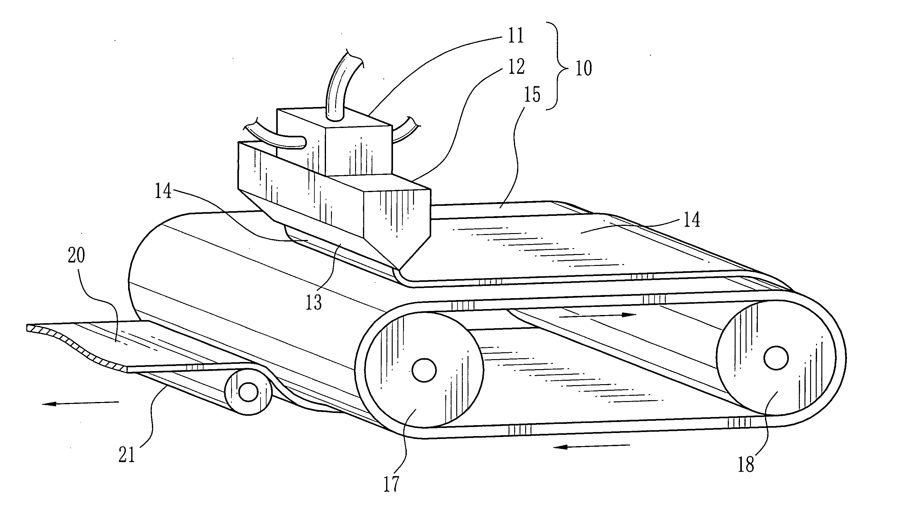
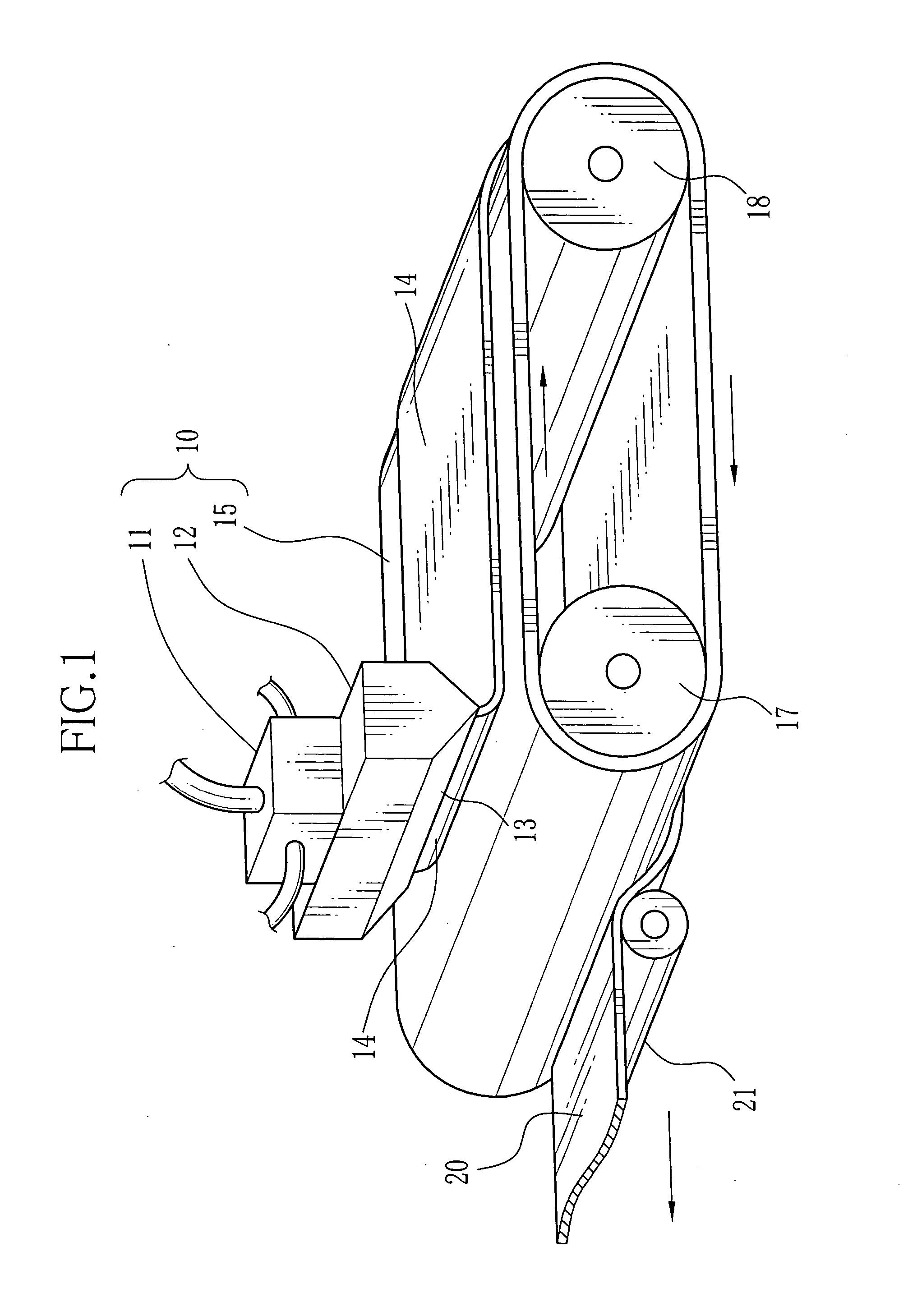
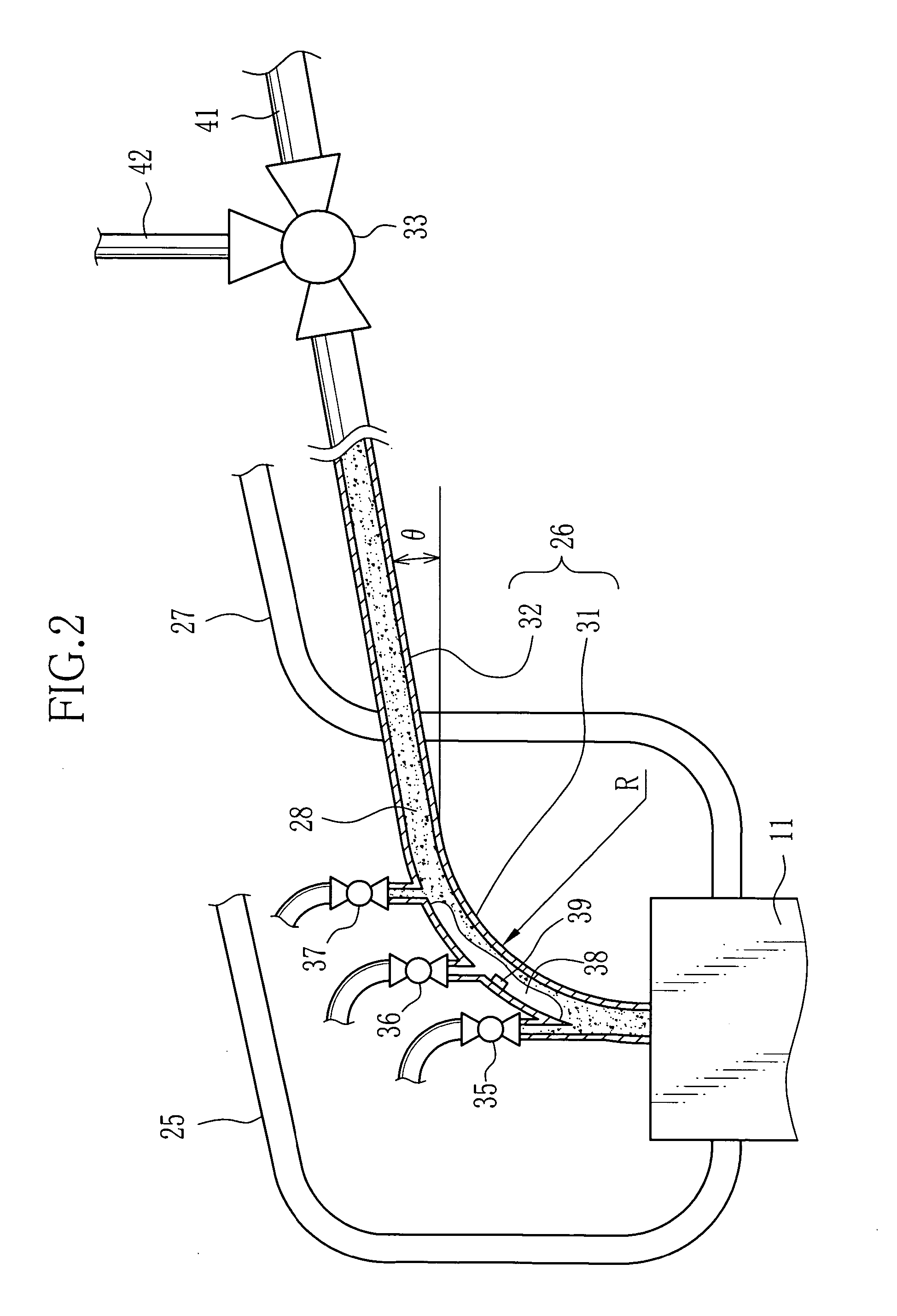
The present invention provides a film casting apparatus that prevents air bubbles from being present in the cast film. This is achieved by using a solution supply pipe with a goose neck portion and a straight pipe portion, which allows air bubbles to escape. The apparatus also includes an air vent valve and an air bubble sensor to monitor and control the air collection process. The use of a cellulose ester solution as the dope results in a high-quality optical application film that is streak-free. The apparatus can also produce a high-quality protective film for a polarizing plate.

Problems solved by technology

However, the solution film-forming method of manufacturing plastic film or resin film can suffer from a trouble that is caused by the air contained in the dope.
That is, when the dope is initially fed to the casting die at the start of operation, the air collects in the leading stream of the dope, and often forms bubbles.
This will result in forming undesirable streaks on the products.
However, it has been found that the apparatus disclosed in Japanese Laid-open Patent Application No. 2000-317961 cannot completely vent the air that collects in the dope supply pipe, so that it is difficult to automatize the starting process of the solution film-forming.

Method used


Image

  • Film casting apparatus, protective film of polarizing plate, and polarizing plate
  • Film casting apparatus, protective film of polarizing plate, and polarizing plate
  • Film casting apparatus, protective film of polarizing plate, and polarizing plate

Examples


examples

[0054] The pipe 26 of the film casting apparatus 10 was formed from a transparent resin, so that the air collection 38 in the pipe 26 may be observed from outside by naked eyes.

[0055] The pipe 26 has an internal diameter of 40 to 150 mm, and more preferably 50 to 90 mm. In the examples and the comparatives, the internal diameter of the pipe 26 was set at 55 mm.

[0056] The solution density of the dope 28 was set at 1300 kg / m3, and the viscosity of the dope was set at 130 Pascal second. The numerical values and the experimental results of the examples and the comparatives are shown in Table 1, wherein “θ” indicates an inclination angle of the straight pipe portion 32, “R” indicates a radius of curvature of the goose neck portion 31, “T” indicates a time lag from the opening of the air vent valves to the start of dope discharging, “L / s” indicates a flow volume (litter per second) of the dope, and “m / s” indicates a flow velocity (meter per second) of the dope.

TABLE 1θRTReynolds(°)(mm...


PUM

PropertyMeasurementUnit
angleaaaaaaaaaa
temperatureaaaaaaaaaa
viscosityaaaaaaaaaa

Abstract

A pipe for supplying a dope to a co-casting die consists of a goose neck portion connected to a feed block of the co-casting die, and a straight pipe portion connected to the goose neck portion. The goose neck portion has a radius of curvature of 50 mm to 400 mm, and the straight pipe portion forms an angle of 0 to 20 degrees to the horizontal plane. Venting valves are opened up at the beginning of dope feeding, and are closed to some extent as the dope comes out. After the air is completely vented out, the venting valves are completely closed. Thereby, an air collection is completely let out from the pipe, a plastic web discharged from die lips of the co-casting die would not contain any air bubbles, it is prevented that the web splashes to put on the die lips, causing steaks on the produced film.

Description

FIELD OF THE INVENTION [0001] The present invention relates to a film casting apparatus for forming plastic film by casting, the plastic film being suitable for optical applications. The present invention relates also to a protective film of a polarizing plate, and the polarizing plate using the protective film that is formed by use of the film casing apparatus of the invention. BACKGROUND ARTS [0002] In recent years, there is an increasing demand for transparent plastic or resin film for optical applications, especially for high-quality protection film of polarizing plates for liquid crystal display devices. For the manufacture of such a plastic film, an apparatus using a solution film-forming method is suitable. [0003] The solution film-forming method uses a solution called dope, which is made by dissolving material flakes with a solvent and adding some additive agents according to the needs, such as plasticizers, UV-absorbers, antidegradants, slipping agents, and a release accele...

Claims


Application Information

Patent Timeline
Patent Type & Authority Applications(United States)
IPC IPC(8): G02B5/30B29C41/24B29C41/28B29C41/32B29C41/34B29K1/00B29L7/00G02F1/1335
CPCB29C41/28Y10S425/812B29C41/32
Inventor NAKAMURA, TOSHIKAZU
Owner FUJIFILM CORP
Learn More