
Radiofrequency surface detection coil

a radiofrequency surface and coil technology, applied in the field of coils for detecting magnetic resonance signals, can solve the problems of coils that are very inefficient at receiving nmr or nqr, are very inefficient at detecting noise, and have a large noise contribution, so as to improve the detection region, improve immunity, and reduce losses

Inactive Publication Date: 2005-03-17
USA AS REPRESENTED BY THE SEC OF THE NAVY THE
View PDF12 Cites 24 Cited by
  • Summary
  • Abstract
  • Description
  • Claims
  • Application Information

AI Technical Summary

Benefits of technology

The invention provides improved immunity to interference from outside RF sources, reduced losses due to nearby electrically conducting materials, and an improved detection region outside the coil, thereby providing increased sensitivity for detecting small quantities of target materials. These properties are advantageous in many applications, such as in buried land mine detection and humanitarian de-mining, security inspections, contraband detection, and in geophysical surveying activities such as well logging.

Problems solved by technology

It is well-known that random thermal noise contributions typically arise from Johnson noise in the RF inspection coil and the first amplifier in the receiver.
In the case where the probe cannot be electrically shielded, a further noise contribution arises from extraneous environmental noise.
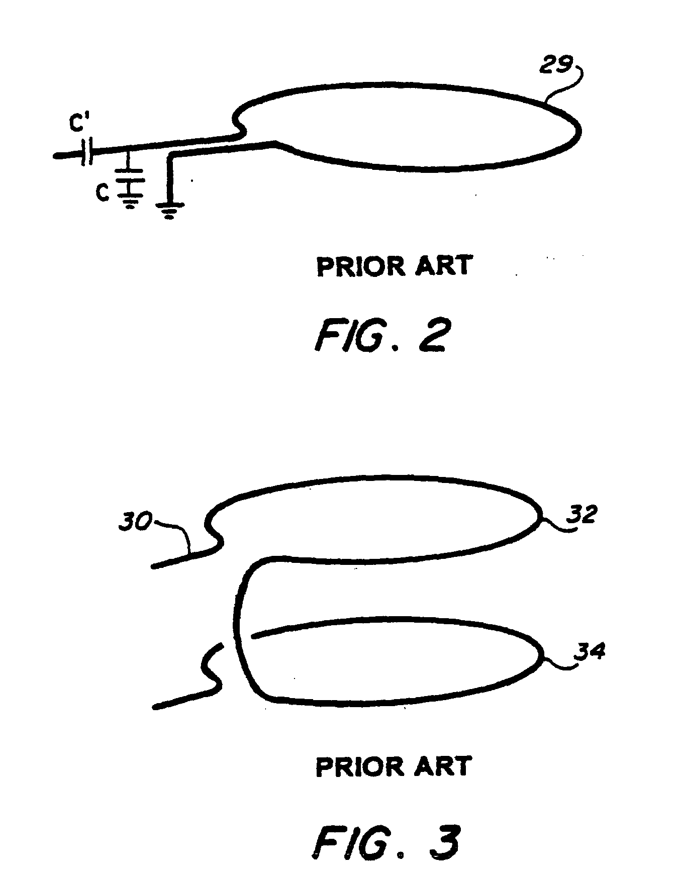
For a conventional simple circular coil (FIG. 2) of radius R the RF magnetic field falls off with distance so the coil is very inefficient at receiving NMR or NQR signals much beyond a distance R. Hence, for applications such as MRI or land mine detection, the distance to the inspection or interrogation region of interest determines the minimum size of the coil which is useful.
Although an RF coil used as a detector in magnetic resonance is not specifically designed to detect or receive radio signals, the detection coil does tend to pick up such unwanted interference.
This radio interference from radio stations or other RF noise sources in the relevant frequency range can overwhelm the magnetic resonance signals of interest.
One solution is to employ an external RF shield surrounding the coil and sample, however, this is impractical in many applications and can unduly increase the cost and size of the system.
These NQR signals are very weak and RF interference is a major problem for such field work.
While a conventional magnetic field gradiometer will reduce environmental magnetic field noise pick-up, the amount of reduction is often insufficient for many applications.
Here the use of an external RF shield, which must surround both the coil and the land mine, is not practical.

Method used


Image

  • Radiofrequency surface detection coil
  • Radiofrequency surface detection coil
  • Radiofrequency surface detection coil

Examples


Embodiment Construction

Reference will now be made in detail to the present preferred embodiments of the present invention, examples of which are illustrated in the accompanying drawings, wherein like reference numerals refer to like elements throughout.

Definition(s): As used herein, the term “asymmetric” when referring to the plural coils of a detector or coil array means that the coils are non-identical, that is, at least one coil of the plurality of coils has a different geometry, different number of turns or windings, or differs in some other physical or operating parameter from the other coil or coils of that embodiment.

Theory Used to Derive Coil Designs

For our purposes it is sufficient to assume that the RF frequency is low enough that displacement current terms can be neglected—that is, we are in the long wavelength limit. For NQR frequencies of the order of 1 MHz and coil dimensions of 1 m or less, this is a reasonable assumption. In addition, for this derivation we assume all regions outsid...


PUM


Abstract

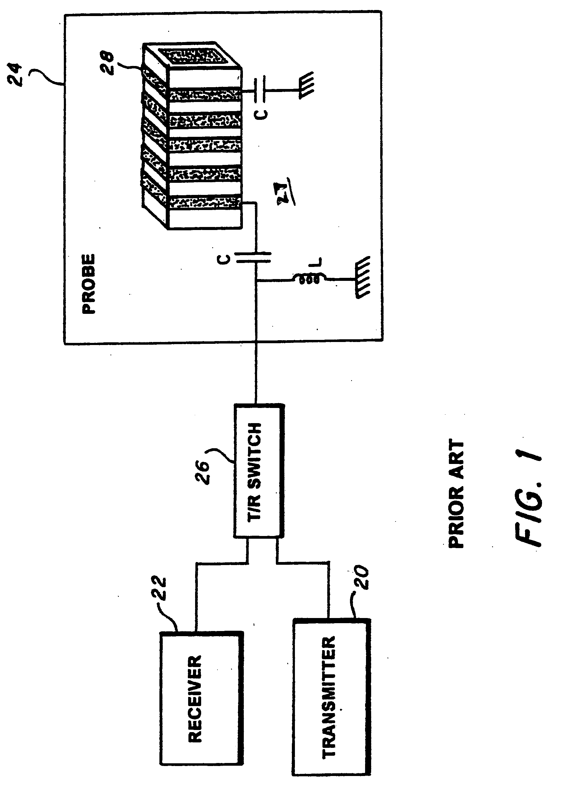
According to the invention, a magnetic field gradiometer detector for detecting a material of interest positioned in a detecting region outside the detector includes a transmitter for generating an output signal at a selected frequency, a receiver for detecting the signal, a probe, and a switch coupling the receiver and transmitter with the probe that alternately connects and disconnects the receiver and transmitter to the probe, switching between transmitting and receiving. The probe includes tuning elements and a gradiometer coil array. The gradiometer coil array includes a first surface coil and a second surface coil wound in an opposite sense, the probe having a first side and an opposite second side, with the first and second surface coils configured asymmetrically such that the probe projects a magnetic field in the outside detecting region adjacent to the first side while being self-shielded on the second side. Accordingly, the material of interest is detected with increased sensitivity and accuracy in the detecting region with the detector shielded from outside RF sources.

Description

TECHNICAL FIELD The present invention relates to a coil for detecting a magnetic resonance signal induced in a sample and, more particularly, to a noise-immune coil having an optimized magnetic field strength in a specified inspection region outside the coil. BACKGROUND ART Magnetic resonance is useful to detect the presence of a specific substance in a sample. For example, generally, radio frequency (RF) radiation at a particular frequency will induce a magnetic resonance signal in a specific substance, but not in other substances. Therefore, the induced magnetic resonance signal can be detected to thereby indicate the presence of the specific substance. It is common to detect a magnetic resonance signal by placing a sample to be measured in or near a tuned, electronically resonant tank circuit. Then, the response of the tank circuit to the electromotive force produced by nuclear or electronic spins in the sample is measured. With Nuclear Magnetic Resonance (NMR), Nuclear Quadru...

Claims


Application Information

Patent Timeline
Patent Type & Authority Applications(United States)
IPC IPC(8): G01V3/10
CPCG01V3/105
Inventor SUITS, BRYAN H.GARROWAY, ALLEN N.
Owner USA AS REPRESENTED BY THE SEC OF THE NAVY THE
Learn More