
Systems and methods for distributed group formation and maintenance in geographically based networks

a technology of distributed group and network, applied in the field of distributed applications, can solve problems such as system failure, complex multi-layered overlapping regions that cannot be easily integrated, and group of active nodes to vary according to the group, so as to achieve the effect of reducing distance measurements

Inactive Publication Date: 2005-03-10
PALO ALTO RES CENT INC
View PDF10 Cites 45 Cited by
  • Summary
  • Abstract
  • Description
  • Claims
  • Application Information

AI Technical Summary

Benefits of technology

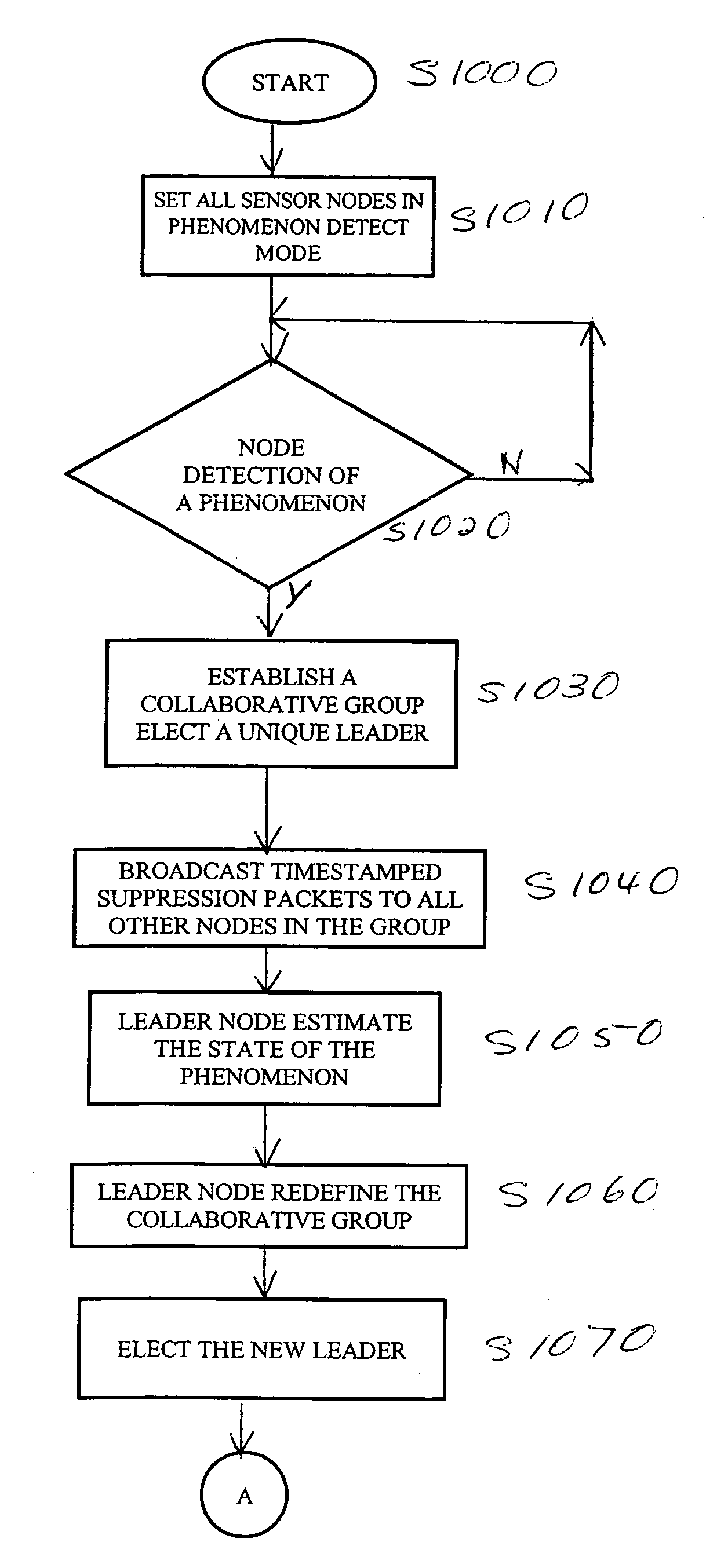
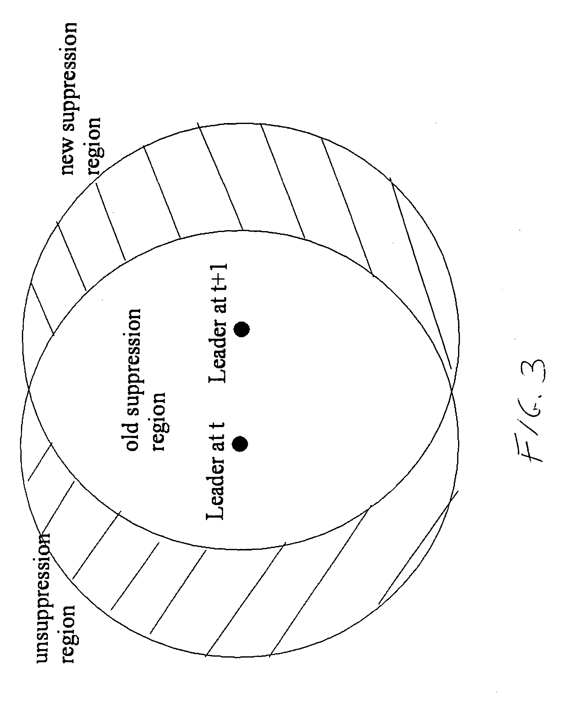
In various exemplary embodiments of the systems and methods according to this invention, sensor node group members are added and dropped as the phenomenon moves. This may be done for scalability, for example. The nodes involved in monitoring a particular phenomenon may be constrained to a finite number of nodes in a local region around the phenomenon in order to minimize the distance measurements that must be transmitted and nodes which are no longer needed may be freed up to monitor new emerging phenomenon once the current phenomenon leaves the region.

Problems solved by technology

Known systems of this type have moved all of the sensor data to central or pre-assigned regional aggregation sites and have not allowed the group of active nodes to vary according to current estimates of the position and extent of the phenomenon.
Scalability and latency generally rule out use of centralized approaches for very high node-count, high phenomenon-count, or very widely-distributed systems, and region-based approaches with fixed aggregation centers are inflexible and often require complex multilayered overlapping regions to work properly.
Wireless sensor networks are particularly ill-suited to centralization because of their limited battery power, and nodes close to aggregation centers must handle a relatively larger quantity of messages and tend to run out of power early, resulting in system failure.
Fixed architectures also tend to concentrate most of the computational work at a single node, which is a highly inefficient use of a system with hundreds or thousands of nodes, and results in unnecessary latency.
However, this has been expensive to use in large sensor networks because it requires flooding each time a subscription is changed.
Sensor networks are subject to certain resource constraints such, as, for example, limited onboard stored energy (e.g., battery) or limited power availability (as with solar power) and limited network communication bandwidth.

Method used


Image

  • Systems and methods for distributed group formation and maintenance in geographically based networks
  • Systems and methods for distributed group formation and maintenance in geographically based networks
  • Systems and methods for distributed group formation and maintenance in geographically based networks

Examples


Embodiment Construction

Various exemplary embodiments of the systems and methods according to this invention assume that each sensor node in the network has the ability to detect new phenomenon and is capable of receiving messages sent to it as well as sending messages to all nodes within a geographic region specified by a bullion function or with the coordinates of nodes within this region. These coordinates may be a tuple of continuous or discrete values. A “tuple” is conventionally defined as an ordered set of values.

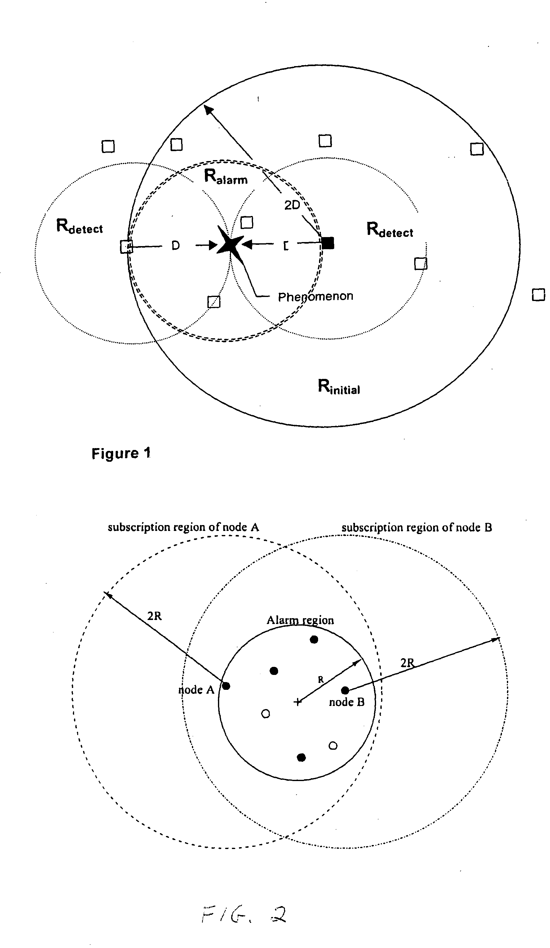
According to various exemplary embodiments of the systems and methods of this invention, a model exists for each sensor node that defines three regions. A first region, labeled RDETECT, is a geographical region containing all locations where a target phenomenon can be detected by a particular sensor node. This geographical region is typically conservative and includes even low probability locations. A second region, labeled RINITIAL, is a geographical region containing all other sensor n...


PUM


Abstract

In a distributed sensor network, one or more devices, for example, forming a collaborative group, are associated with a physical phenomenon based on geographical proximity. The sensor network is capable of detecting new phenomena and changing the membership of the collaborative group as the phenomenon changes. Sensors not associated with a detected phenomenon are available to detect new phenomenon, and one group may exist per phenomenon. Upon detection of a phenomenon, a group of nodes is formed and a leader node is elected. As the phenomenon changes over time, new devices come into proximity of the phenomenon and are prevented from forming independent groups associated with the phenomenon. This accomplished in a decentralized way with communication restricted to local neighbors. In a tracking sensor network using a relatively small number of sensors, the sensors are active and maintain a coherent belief associating their measurements with a single common vehicle.

Description

BACKGROUND OF THE INVENTION 1. Field of Invention The systems and methods of the invention are directed to distributed applications such as sensor networks. 2. Description of Related Art The U.S. Patent Application Publication No. 2002 / 000920 discloses detection and maintenance of moving vehicle data in an array of sensors. All vehicles are identified at a fixed entry point and are sensed by only a single sensor at a time. U.S. Pat. No. 6,366,913 discloses techniques for dynamic maintenance of group membership based on time-varying attributes, including position. The techniques operate through a centralized directory server. U.S. Pat. No. 6,275,847 discloses a self-configuring distributed processing system which is pre-configured into cells. U.S. Patent Application Publication No. 2002 / 0057340 discloses an integrated fixed and / or wireless network for monitoring and processing remote indoor local movable objects where an object database or functionally equivalent data structur...

Claims


Application Information

Patent Timeline
IPC IPC(8): H04W4/38H04L12/56H04L29/06H04L29/08H04W64/00H04W84/20
CPCH04L29/06H04W4/04H04W64/00H04L69/329H04L67/125H04L67/10H04W84/20Y04S40/18H04W4/38H04L9/40
Inventor REICH, JAMES E.LIU, JUANLIU, JIE
Owner PALO ALTO RES CENT INC
Learn More