
Tire inspection apparatus and method

a technology of inspection apparatus and tires, applied in vehicle tyre testing, force measurement by measuring optical property variation, instruments, etc., can solve the problems of high-sensitivity film output, high cost, and special viewing device, and the cost of individual tire testing and film based shearographic tire testing machines

Inactive Publication Date: 2005-03-10
RAVEN ENG
View PDF26 Cites 72 Cited by
  • Summary
  • Abstract
  • Description
  • Claims
  • Application Information

AI Technical Summary

Benefits of technology

[0011] It is an object of the present invention to provide a tire testing technique and apparatus which permits the utilization of coherent light and reflection of such light to be cap

Problems solved by technology

While some systems for shearography have an output such as the display of computerized systems of the '874 patent, many of the systems utilized are such that they have an output of highly sensitive film which is extremely costly and requires a special viewing device.
Further, film based shearographic tire testing machines (and individual tire tests) are typically very expensive therefore a limited number are utilized in the industry within individual plants.
Thus each point on the object generates two rays and the result is an interference image formed by the optical interference of two laterally displaced images of the same object.

Method used


Image

  • Tire inspection apparatus and method
  • Tire inspection apparatus and method
  • Tire inspection apparatus and method

Examples


Embodiment Construction

[0023] Definitions

[0024] Anomaly is defined as a defect in a tire which can generally be characterized as air trapped in a cured tire as a result of variations in the thickness of the tire components; porosity and voids in the tire, a separation, an undercure of the tire, trapped air and bubbles; low interply adhesion, poor cord adhesion, bare wires, broken cords, and machine building errors.

[0025] Bitmap is a data file or structure which corresponds bit for bit with an image displayed on a screen, preferably in the same format as it would be stored in the display's video memory or alternatively as a device independent bitmap. A bitmap is characterized by the width and height of the image in pixels and the number of bits per pixel which determines the number of shades of grey or colors it can represent.

[0026] Coherent light is a light having a single wavelength, frequency and phase. It is also radiant electromagnetic energy of the same, or almost the same wavelength, and with def...


PUM


Abstract

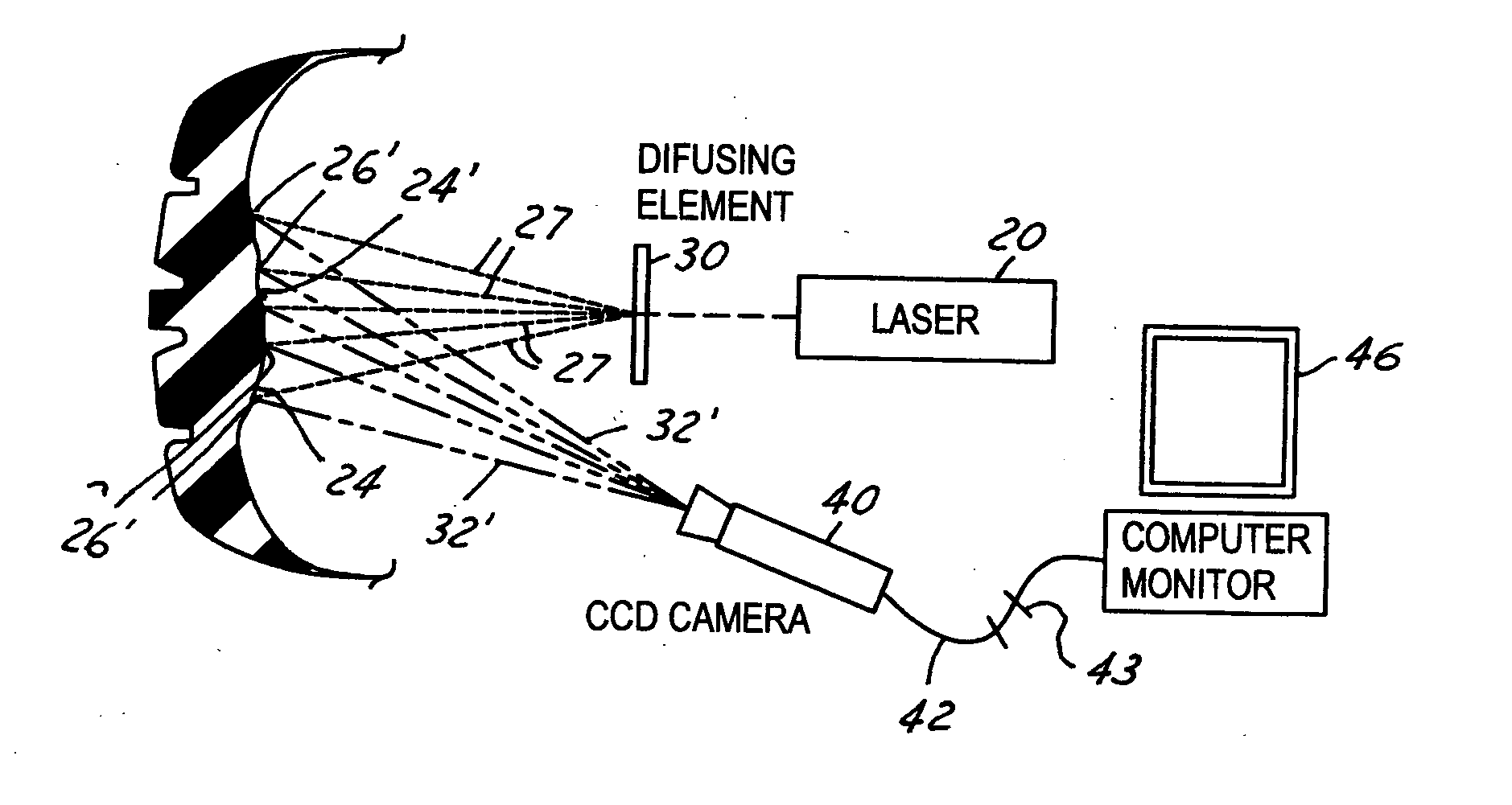
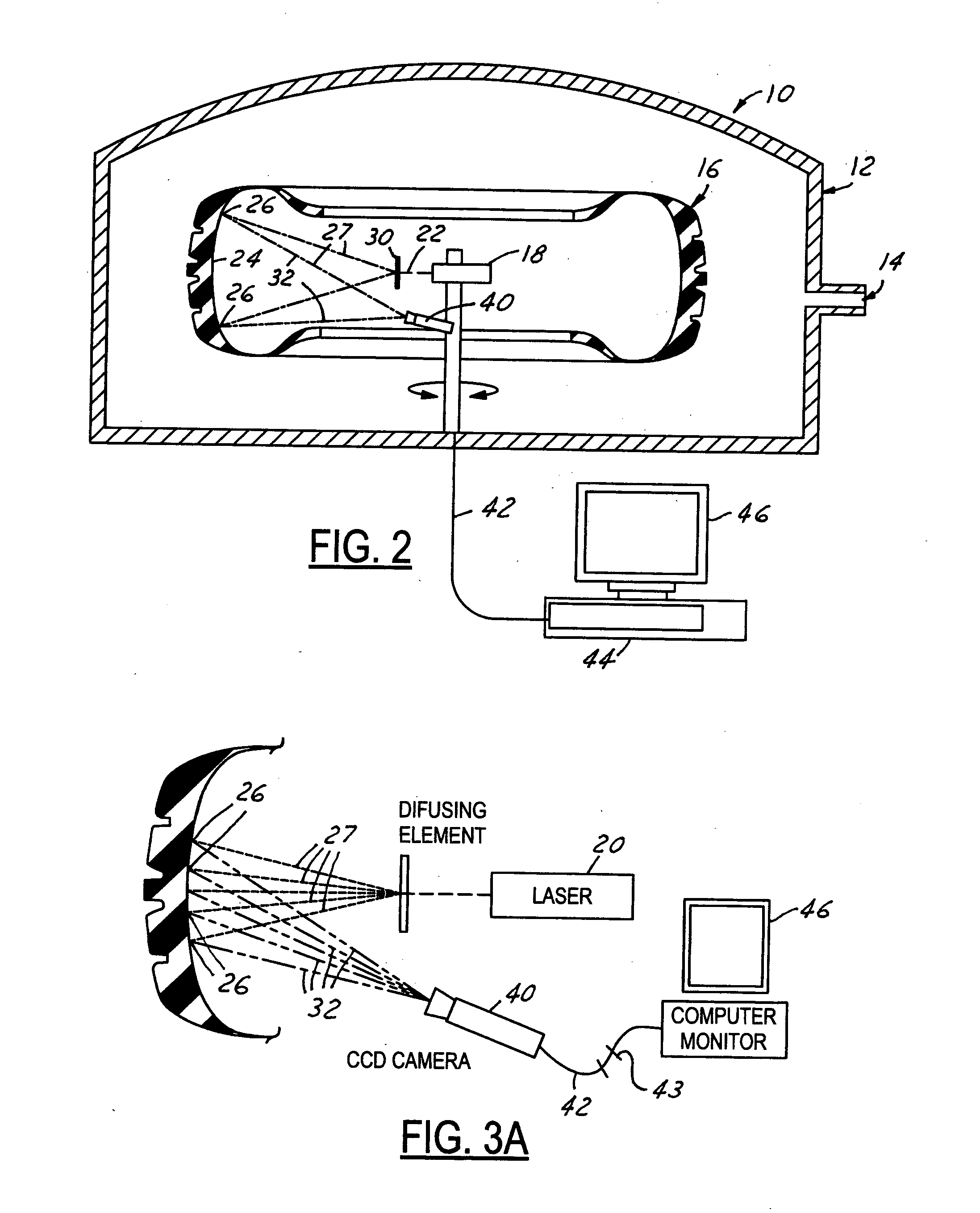
Described is an anomaly detector apparatus 10 for detecting an anomaly in a tire comprising: a source of coherent light 18 to shine the light 27 directly onto the tire surface 24 and the light being reflected 32 from the tire; a stressing apparatus 12 which can stress the tire; a reflected light receiving apparatus 40 for receiving the light 32 reflected directly from the tire surface 24 when the tire is in a stressed and unstressed condition; a processor 44 which compares images of reflected light from the reflected light receiving apparatus 40 when the tire is stressed and unstressed thereby ascertaining an anomaly in the tire and generates an output from the comparison; and a display apparatus 46 electronically connected to the processor for displaying the output from the processor.

Description

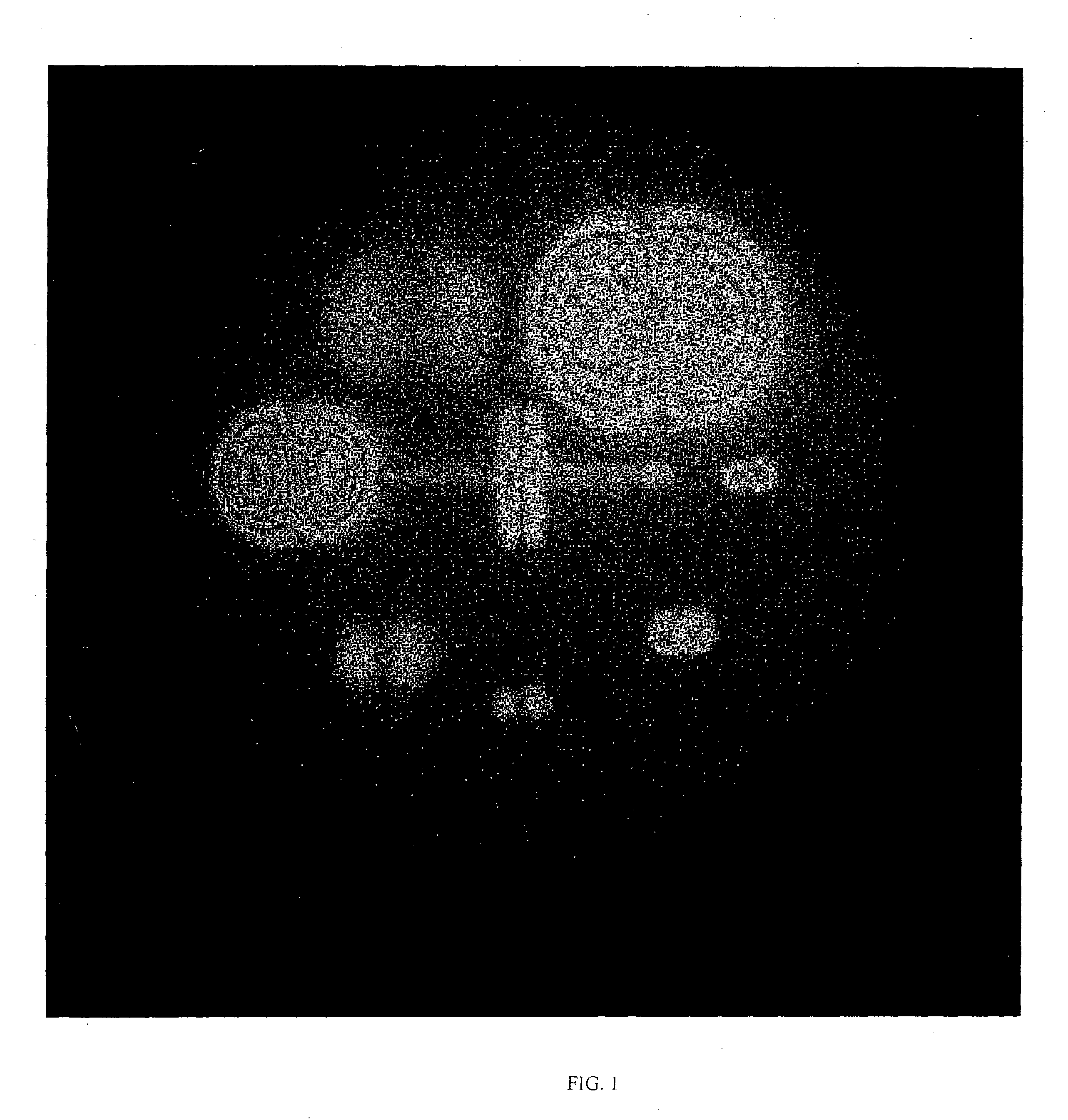
FIELD OF THE INVENTION [0001] The present invention pertains to the field of Non-Destructive Testing. (NDT) In particular the invention pertains to such testing of tires, utilizing a computer for automated output display of an image of the tested tire. BACKGROUND OF THE INVENTION [0002] For many years the standard practice for calibrating shearographic / holographic tire testing machines has been ASTM F1364-92. This test method describes the construction and use of a calibration device for demonstrating the anomaly detection capability of an interferometric laser imaging non-destructive tire inspection system. A typical shearographic fringe pattern resulting from such testing technique is shown in FIG. 1. [0003] As has been described in U.S. Pat. No. 6,433,874 the technique of shearing interferometry, or shearography involves the interference of two laterally-displaced images of the same object to form an interference image. Conventional shearographic methods require that a first inte...

Claims


Application Information

Patent Timeline
IPC IPC(8): G01B11/16G01M17/02
CPCG01M17/027G01B11/162G01B11/24G01B11/22B60C25/007G01L17/005
Inventor SHAW, EUGENE L.WRIGHT, FORREST S.
Owner RAVEN ENG
Learn More