
Adaptive transmit diversity with quadrant phase constraining feedback

a quadrant phase and feedback technology, applied in diversity/multi-antenna systems, modulation, electromagnetic wave modulation, etc., can solve the problem that the technique still consumes a large number of bits, and achieve the effect of simple feedback

Inactive Publication Date: 2005-03-03
MITSUBISHI ELECTRIC RES LAB INC
View PDF6 Cites 74 Cited by
  • Summary
  • Abstract
  • Description
  • Claims
  • Application Information

AI Technical Summary

Benefits of technology

The invention provides an adaptive transmit diversity scheme with simple feedback for a wireless communication systems.
It is an object of the invention to achieve better system performance with less feedback information and less computations than conventional transmit diversity methods.
With simple linear operations at both the transmitter and receiver, the method requires only one bit of feedback information for systems with two antennas (M=2) at the transmitter and one antenna at the receiver.
The computational complexity of the invented method is much lower compared with optimum quantized TxAA closed loop technique with the same amount of feedback.

Problems solved by technology

That technique still consumes a large number of bits.

Method used


Image

  • Adaptive transmit diversity with quadrant phase constraining feedback
  • Adaptive transmit diversity with quadrant phase constraining feedback
  • Adaptive transmit diversity with quadrant phase constraining feedback

Examples


Embodiment Construction

FIG. 1 shows a baseband representation of a diversity system 100 according to our invention. Our system has M antennas 101 at a transmitter 10, for example, a base station, and one antenna 102 at a receiver 20, e.g., a cellular telephone.

At a time instant k, a modulated symbol sk 103 is linearly encoded 110 at the transmitter in a space domain according to a space encoding vector 111

pk=[p1(k), p2(k), . . . , pM(k)]εC1×M.

The encoded transmit data 112 are xk=[x1(k), x2(k), . . . , xM(k)]=pk·sk, with xm(k) being transmitted at the mth transmit antenna 101.

In our adaptive transmit diversity method, the space encoding vector pk 111 is determined 120 at the transmitter according to feedback information 121 determined from space decoding 130 of the received signal 105 at the receiver.

Specifically, the feedback information 121 relates to phase differences between pairs of received signals in a fading transmission channel 115. It is desired to minimize the phase difference between sig...


PUM


Abstract

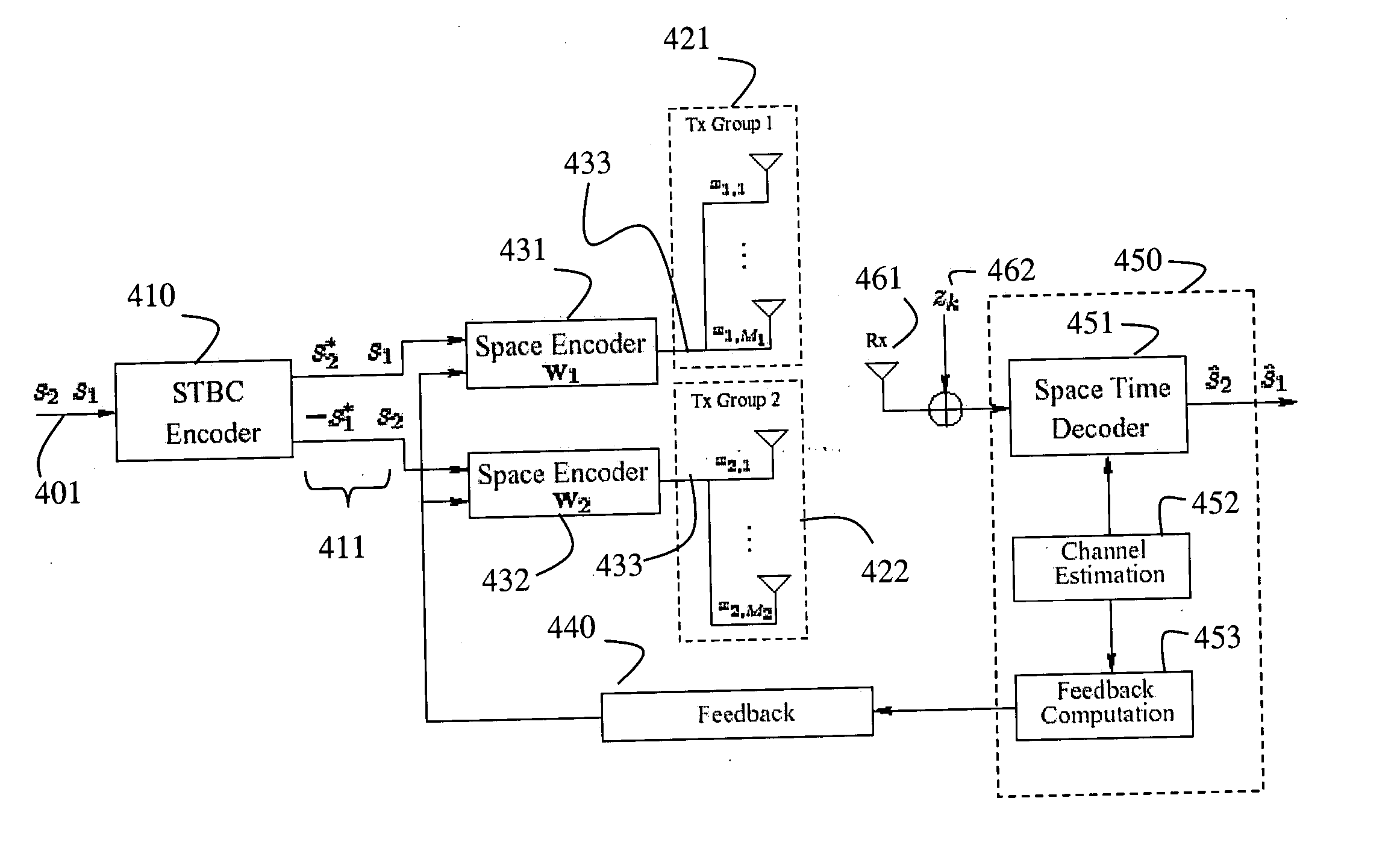
A wireless communication system includes a transmitter and a receiver. The transmitter includes multiple groups of transmit antennas. Input symbols are generated and then orthogonal space-time block is encoded to produce a data stream for each group of transmit antennas. Each data stream is adaptively linear space encoded to produce an encoded signal for each transmit antenna of each group according to feedback information for the group. The receiver includes a single receive antenna, a module for measuring a phase of a channel impulse response for each transmit antenna. The feedback information is determined independently for each group of transmit antennas from the channel impulse responses. The feedback information for each group of transmit antennas is sent to the transmitter.

Description

FIELD OF THE INVENTION This invention relates generally to transmit diversity gain in wireless communications networks, and more particularly to maximizing the diversity gain adaptively in transmitters. BACKGROUND OF THE INVENTION The next generation of wireless communication systems is required to provide high quality voice services as well as broadband data services with data rates far beyond the limitations of current wireless systems. For example, high speed downlink packet access (HSDPA), which is endorsed by the 3rd generation partnership project (3GPP) standard for wideband code-division multiple access (WCDMA) systems, is intended to provide data rates up to 10 Mbps or higher in the downlink channel as opposed to the maximum 384 Kbps supported by the enhance data rate for GSM evolution (EDGE), the so-called 2.5G communication standard, see 3GPP: 3GPP TR25.848 v4.0.0, “3GPP technical report: Physical layer aspects of ultra high speed downlink packet access,” March 2001, and...

Claims


Application Information

Patent Timeline
Patent Type & Authority Applications(United States)
IPC IPC(8): H04B7/06H04L1/06
CPCH04B7/0626H04B7/0658H04L1/0693H04L1/0618H04B7/0669
Inventor WU, JINGXIANZHANG, JINYUNMOLISCH, ANDREAS
Owner MITSUBISHI ELECTRIC RES LAB INC
Learn More