
Reconfigurable topology for switching and linear voltage regulators

Active Publication Date: 2005-03-03
TEXAS INSTR INC
View PDF4 Cites 70 Cited by
  • Summary
  • Abstract
  • Description
  • Claims
  • Application Information

AI Technical Summary

Benefits of technology

[0014] It is therefore an object of this invention to provide an integrated circuit that efficiently includes multiple voltage regulators of different types.

Problems solved by technology

However, linear voltage regulators are somewhat limited in their performance.
However, switching regulators are typically more costly to implement than are linear regulators.
The circuitry for controlling the switching operation is typically more complex than in the linear regulator, and involves additional devices and intelligence.
As well known in the art, significant inductance cannot be readily realized in a solid-state integrated circuit, thus requiring an external component to be connected to effect the switching regulator function.
In this situation, the end equipment manufacturer is faced with either maintaining inventory of separate integrated circuits for the separate implementations, or with using a less-than-optimal voltage regulator in some system implementations.
Certain elements within conventional voltage regulators can occupy significant chip area.
For example, feedback capacitors for error amplifiers within the sense and control loop of conventional voltage regulators can be quite large.
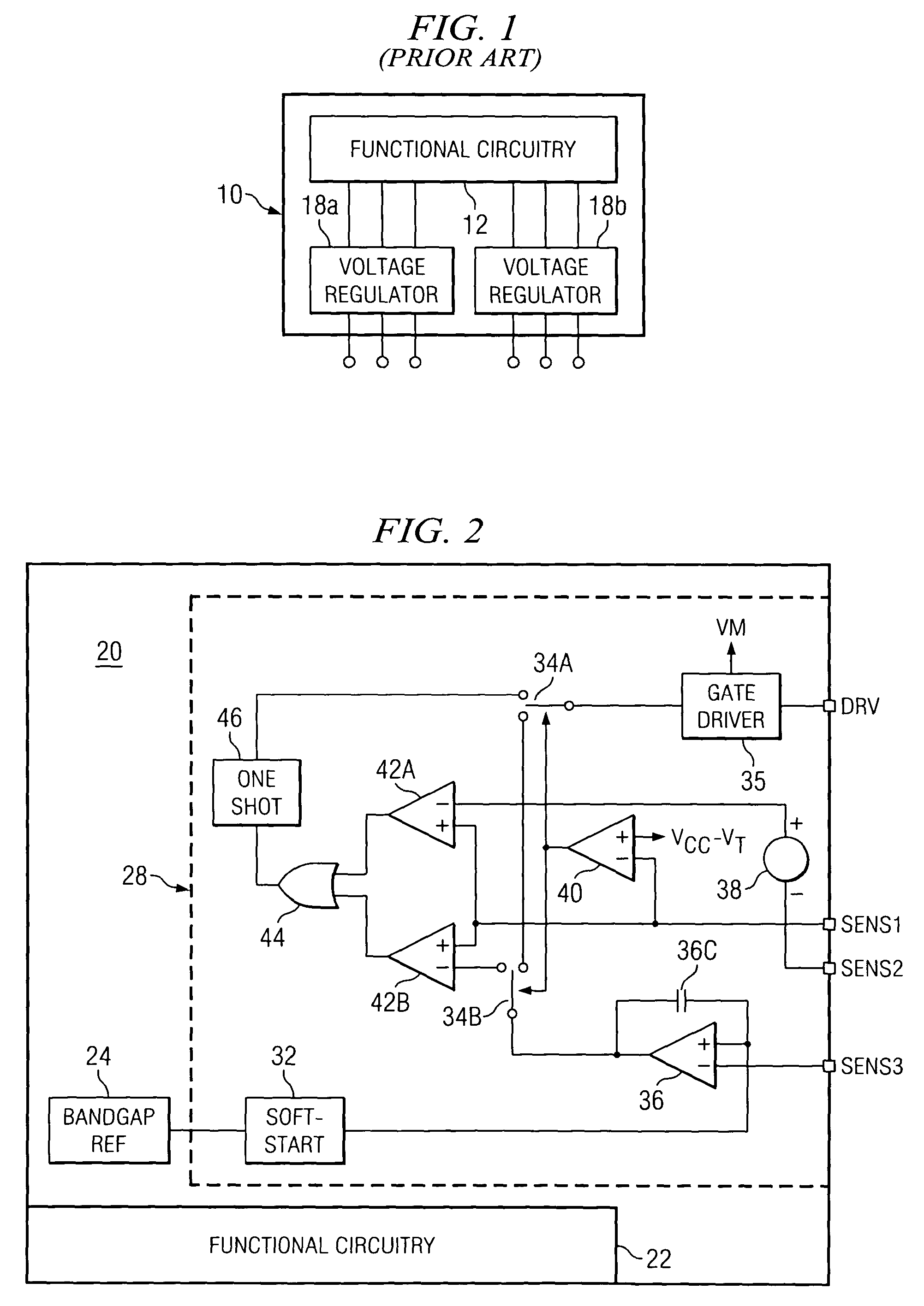
The implementation of two separate voltage regulators according to conventional techniques is therefore costly in terms of chip area.
In these large scale integrated circuits, the provision of each external terminal can be quite costly, not only in package size and complexity, but also in the chip area required to safely route signals to the external terminal.

Method used


Image

  • Reconfigurable topology for switching and linear voltage regulators
  • Reconfigurable topology for switching and linear voltage regulators
  • Reconfigurable topology for switching and linear voltage regulators

Examples


Embodiment Construction

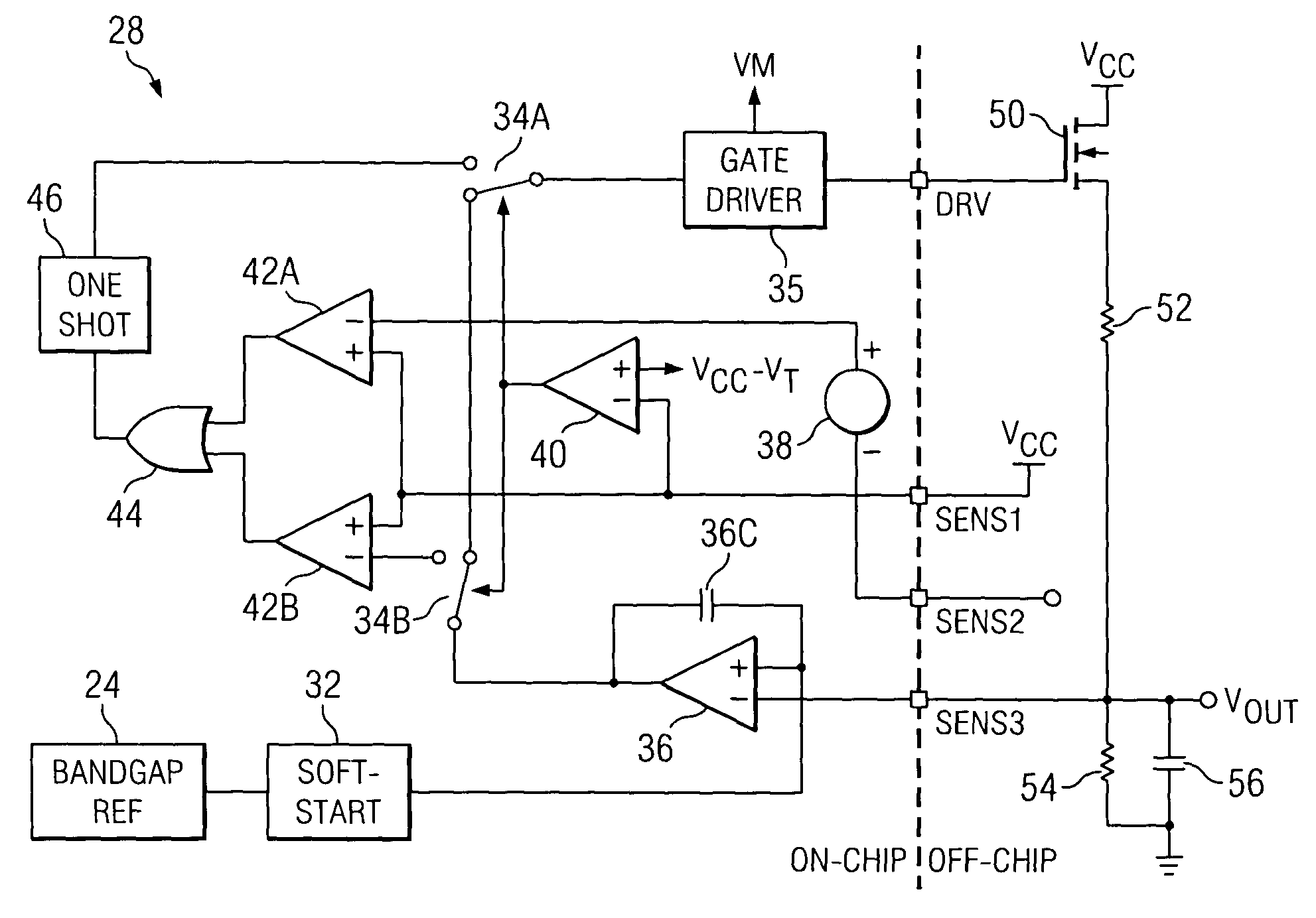
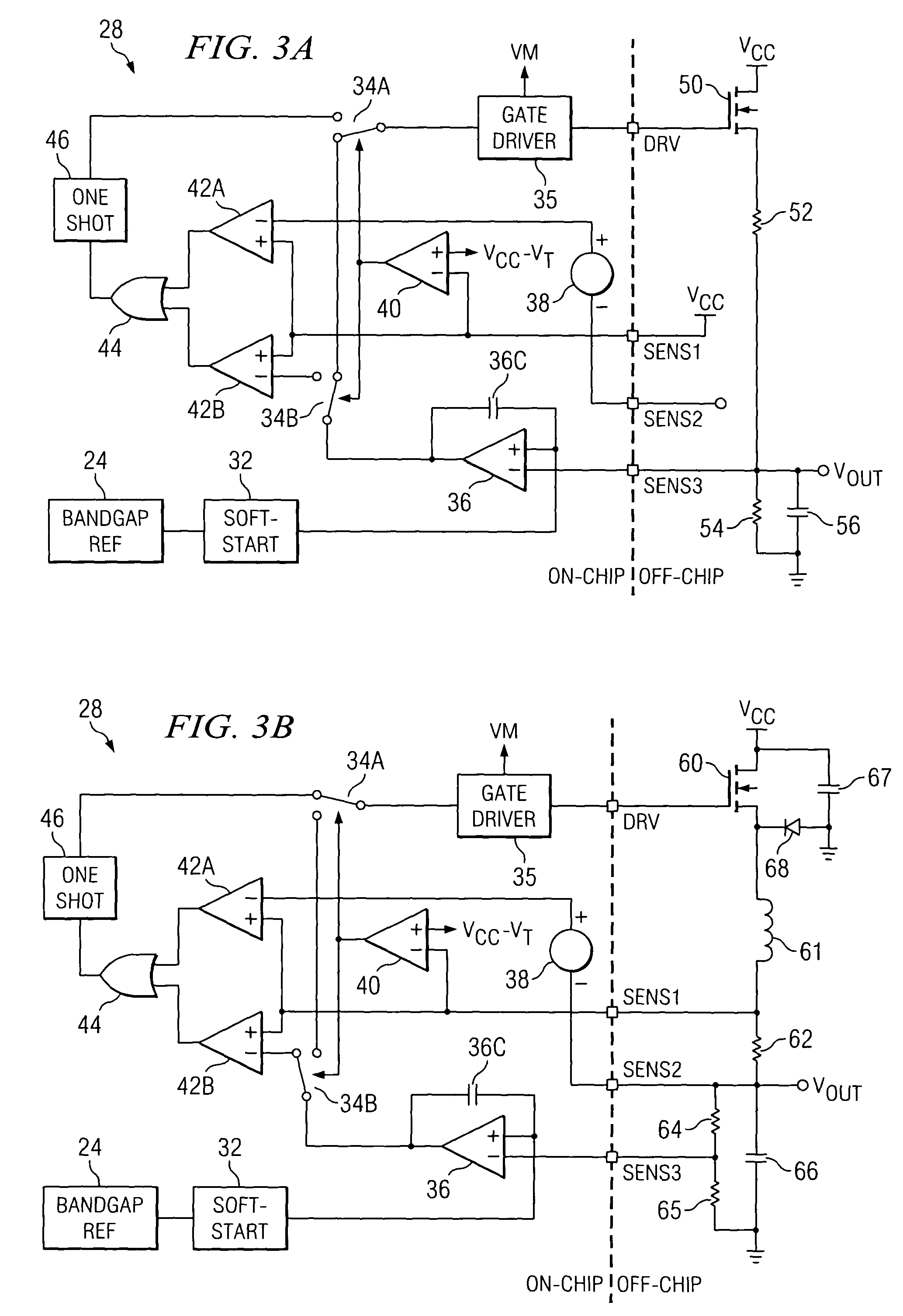
[0029] The present invention will be described in connection with its preferred embodiment, namely as an integrated circuit having additional functional circuitry, such as a spindle motor controller as used in connection with a computer disk drive, because this invention is contemplated to be especially useful in such an application. However, it will be understood by those skilled in the art having reference to this specification that this invention will also be beneficial in other applications, including integrated circuits of different ultimate functions, and also as a stand-alone voltage regulator device. Accordingly, it is to be understood that the following description is provided by way of example only, and is not intended to limit the true scope of this invention as claimed.

[0030] Referring first to FIG. 2, integrated circuit 20 according to the preferred embodiment of the invention will now be described. Integrated circuit 20, in this example, includes functional circuitry ...


PUM


Abstract

A configurable voltage regulator (28; 128) operable in either of two selectable modes or topologies is disclosed. In one disclosed embodiment, the voltage regulator (28) can operate as a linear regulator or a switching regulator. A gate driver (35) and an error amplifier (36) is used in each mode. Configuration switches (34) are controlled by a configuration amplifier (40) to connect the error amplifier (36) to the gate driver (35) in the linear regulator mode, or to connect the error amplifier (36) to circuitry (42, 44, 46) for controlling the gate driver (35) in switching regulator mode. In another disclosed embodiment, the voltage regulator (128) generates a negative polarity regulated voltage according to a switching regulator or charge pump topology.

Description

CROSS-REFERENCE TO RELATED APPLICATIONS [0001] This application is related to copending application Ser. No. ______, entitled “A Reconfigurable Topology for Switching and Charge Pump Negative Polarity Voltage Regulators”, and filed contemporaneously and commonly assigned with this application.STATEMENT REGARDING FEDERALLY SPONSORED RESEARCH OR DEVELOPMENT [0002] Not applicable. BACKGROUND OF THE INVENTION [0003] This invention is in the field of semiconductor integrated circuits, and is more specifically directed to voltage regulators implemented in a large scale integrated circuit. [0004] Many modern electronic devices and systems, particularly those performing control and other analog functions, rely upon the generation and use of a stable regulated voltage. For example, integrated circuits for controlling motors, such as disk drive controllers in a desktop or laptop computer system or workstation, require a regulated voltage to supply the voltages required by the digital circuits...

Claims


Application Information

Patent Timeline
IPC IPC(8): G05F1/56
CPCG05F1/56
Inventor TRAFTON, FREDRICK W.GUNAWAN, SUJANTO
Owner TEXAS INSTR INC
Learn More