Method and apparatus for high pressure water jet lancing of foreign materials from surfaces of a nuclear power reactor

a nuclear power reactor and foreign material technology, applied in the direction of cleaning process and apparatus, chemistry apparatus and process, hollow article cleaning, etc., can solve the problems of difficult removal process, high radiation dosage to personnel, and difficulty in effectively removing all crud prior to maintenance and inspection of the reactor

Inactive Publication Date: 2005-03-03
HENNIGAN ENG
View PDF4 Cites 12 Cited by
  • Summary
  • Abstract
  • Description
  • Claims
  • Application Information

AI Technical Summary

Benefits of technology

[0007] The present invention discloses a remotely controllable apparatus and technique for the removal of “CRUD” from the annulus area around and inside the thermal sleeve at the lower elbow assembly of the jet pump riser pipe assembly and other nozzle configurations and surfaces within a nuclear Reactor Pressure Vessel. The inventive apparatus comprises a flexible, high pressure water jetting lance assembly for delivering intense water pressure (up to 20,000 psi) via nozzle(s) directly to the areas containing the highly radioactive “CRUD” material, thereby causing excision of the CRUD. The flexible lance assembly is positioned to the contamination site with either a guide tube having any predetermined shape or a positioning member, either of which may be torqued and manipulated until the nozzle end of the lance assembly is in position.
[0008] According to one aspect of the invention, an apparatus for removal of contaminants from remote surfaces comprises: an elongate delivery tube having a lumen extending therethrough and having a first end and a second end connectable to a source of high pressured fluid to allow fluid communication with the delivery tube lumen; a nozzle operatively coupled to the first end of the delivery tube, the nozzle having at least one orifice in fluid communication with the delivery tube lumen; and means for positioning the nozzle in the proximity of the contaminants. In one embodiment of the invention, the means for positioning the nozzle comprises an elongate guide tube having a lumen extending therethrough and into which the elongate delivery tube is disposed. The guide tube may have a distal portion thereof with a bend radius that deviates from the main axis of the guide tube by an off axis angle of between 0° and 180°. In another embodiment, the means for positioning the nozzle comprises an elongate positioning member and means for securing the positioning member to the elongate delivery tube. In various other embodiments, the apparatus further comprises an adaptor with either an L-shaped or T-shaped lumen operatively coupling one or more nozzles to the delivery tube, or, any of a sensor, transducer, and imaging device carried at the distal end of the guide tube and operatively coupled to a processing unit at the proximal end of the guide tube.
[0009] According to a second aspect of the invention, a method for removal of contaminants from remote surfaces comprises: (a) providing the high pressure lancing apparatus comprising: (i) an elongate delivery tube having a lumen extending therethrough and having a first end and a second end connectable to a source of high pressure fluid so as to allow fluid communication with the delivery tube lumen, the delivery tube having a second end, (ii) a nozzle operatively coupled to the first of end of the delivery tube and having at least one orifice in fluid communication with the lumen of the delivery tube, and (iii) means for positioning the nozzle; (b) manipulating the means for positioning the nozzle so that the nozzle is disposed in proximity of the contaminants; (c) providing high pressure fluid from a source to the lumen of the elongate delivery tube; and (d) directing high pressure fluid emanating from the nozzle toward the contaminants.
[0010] According to one embodiment of the method, the means for positioning the nozzle comprises an elongate guide tube having a lumen extending therethrough and into which the elongate delivery tube is disposed and wherein (b) comprises: (b1) positioning a distal end of the guide tube in the proximity of the contaminants; and (b2) manipulating the elongate delivery tube within the lumen of the guide tube so that the nozzle extends beyond the distal end of the guide tube. According to another embodiment of the method, the means for positioning the nozzle comprises an elongate positioning member secured to the elongate delivery tube and wherein (b) comprises: (b1) manipulating the elongate positioning member so that the nozzle is disposed in proximity of the contaminants. According to yet another embodiment of the method, the nozzle of the lancing apparatus has a plurality of orifices and wherein (b) comprises: (b1) directing high pressure fluid from one of the nozzle orifices in a direction other than the toward the contaminants.
[0011] According to still another embodiment of the method, the lancing apparatus further comprises a plurality of nozzles operatively coupled to the elongate delivery tube and in fluid communication with the lumen of the elongate delivery tube and wherein (b) comprises:(b1) directing high pressure fluid from one of the nozzles in a direction substantially opposite the direction from which high pressure fluid is emanating from another of the plurality of nozzles. According yet another embodiment of the method, the lancing apparatus further comprises a sensor carried near the first end of the elongate delivery tube and in communication with a processing unit near the second end of the elongate delivery tube and wherein the method further comprises: (e)sensing a condition in the proximity of the nozzle; and (f) transmitting signals associated with the condition from the sensor to the processing unit.

Problems solved by technology

However, because of the size, shape and design of many reactors, coupled with the fact that the reactor or portions thereof are immersed in water, the removal process can be difficult to perform.
These formations and deposits are very undesirable when maintenance and inspections are being performed and can result in high rates of radiation dosage to personnel.
Because of the size, shape and water depth of the spaces in which the CRUD accumulates it is very difficult to effectively remove all CRUD prior to maintenance and inspections of the reactor.
In addition, the access paths to the remote locations in which CRUD accumulates are often at least partially obstructed with other elements, e.g. plates, brackets, etc. which increased the difficulty in accessing the site of the CRUD.

Method used


Image

  • Method and apparatus for high pressure water jet lancing of foreign materials from surfaces of a nuclear power reactor
  • Method and apparatus for high pressure water jet lancing of foreign materials from surfaces of a nuclear power reactor
  • Method and apparatus for high pressure water jet lancing of foreign materials from surfaces of a nuclear power reactor

Examples


Embodiment Construction

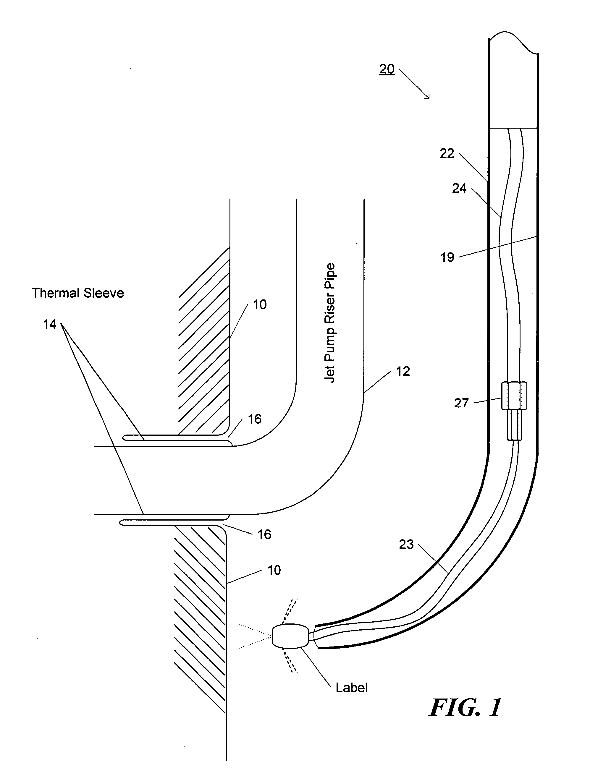
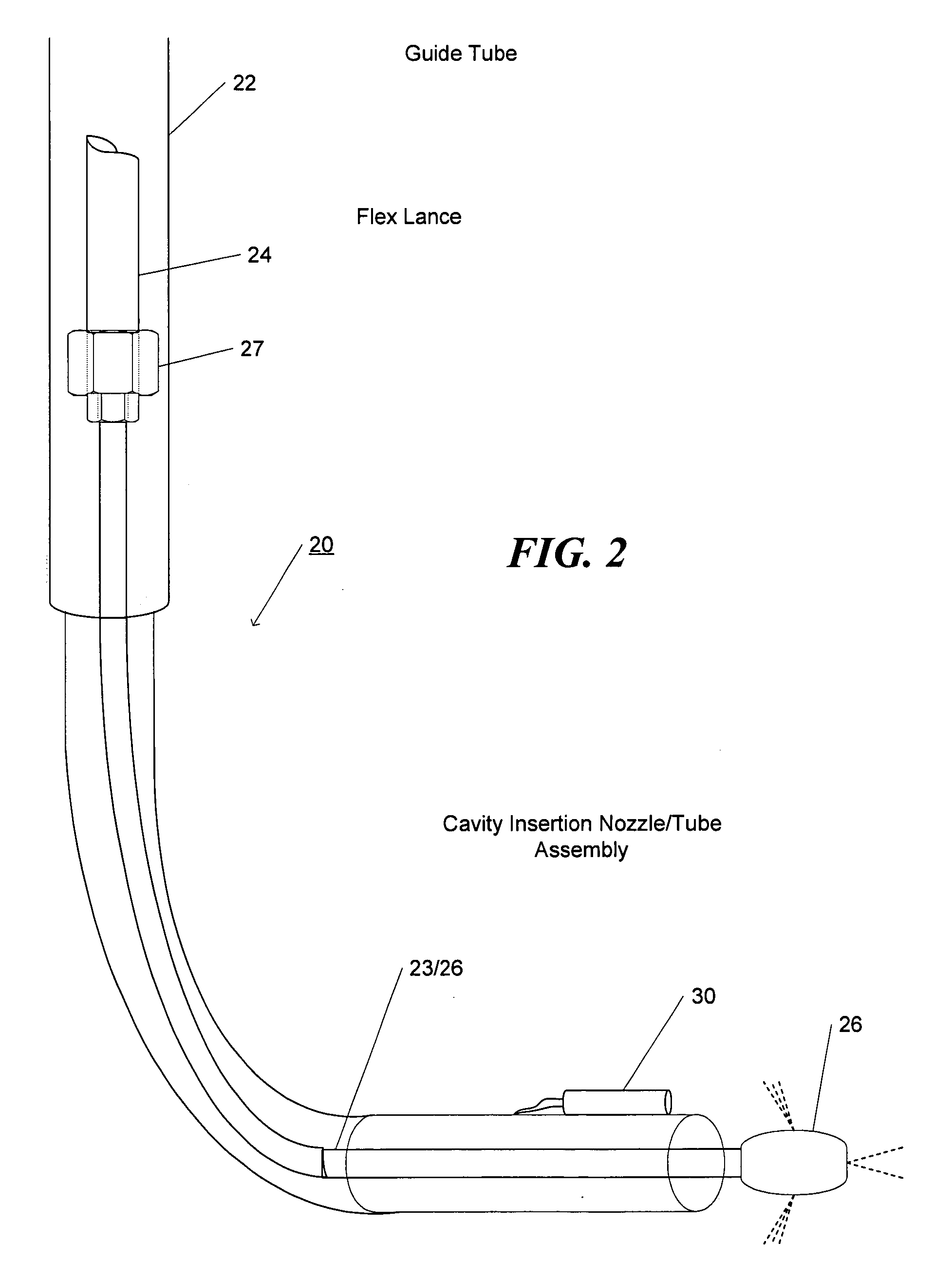
[0030]FIGS. 1-3 illustrate a remotely controllable apparatus 20 for the removal of “CRUD” from remote areas of limited accessibility within a nuclear Reactor Vessel, including the annulus area around and inside the thermal sleeve at the lower elbow assembly of the jet pump riser pipe assembly. The apparatus 20 comprises a multi-section guide tube assembly 22 encasing a high pressure water jetting lance assembly 25 comprising a feeder lance 24 intercoupled to a cleaning lance 23 which carries a nozzle 26 at an end thereof. The more proximal end of lance assembly 25, feeder lance 24, is attachable to a high pressure pump system 7 with a working pressure capability of 20,000 psi, through appropriate couplings rated for the working pressure, as determined by the designer. In apparatus 20, the jetting lance assembly 25 is movably disposed within a central lumen 19 of guide tube 22 to enable the positioning of cleaning lance 23 and nozzle 26 relative to do the distal tip of the guide tube...


PUM


Abstract

A remotely controllable apparatus and technique for the removal of “CRUD” from surfaces within a nuclear Reactor Pressure Vessel includes a flexible, high pressure water jetting lance assembly for delivering intense water pressure (up to 20,000 psi) via nozzle(s) directly to the areas containing the highly radioactive “CRUD” material. The jetting lance assembly is positioned to the contamination site with either a guide tube having any predetermined shape and into which the lance assembly is disposed or a positioning member attached to the lance assembly, either of which may be torqued and manipulated until the nozzle end of the lance assembly is in position. Various other embodiments include multiple nozzles, adapters that have a specific shaped lumen, one or more sensor devices is communication with processing units near the proximal end of the apparatus.

Description

RELATED APPLICATIONS [0001] This application claims priority to United States Provisional Patent Application Ser. No. 60 / 405,384, filed Aug. 23, 2002, by Charles S. Hacquebord, entitled Method and Apparatus for Decontamination of Nuclear Reactor, the subject matter of which is incorporated herein by reference for all purposes. FIELD OF THE INVENTION [0002] This invention relates to apparatus for decontamination radioactive material, and, more specifically, to a remotely controllable apparatus for the removal of “CRUD” from the nozzles and thermal sleeves of a nuclear reactor pressure vessel. BACKGROUND OF THE INVENTION [0003] Nuclear reactors require periodic maintenance and inspection to operate safely. Part of such maintenance includes the inspection of welds and components within the reactor pressure vessel. In doing so, personnel are subjected to high levels of radiation (dose). Therefore removal of CRUD from various reactor surfaces is required to provide a low dose and safe wo...

Claims


Application Information

Patent Timeline
Patent Type & Authority Applications(United States)
IPC IPC(8): B05B1/02B05B1/14B05B7/02B05B9/01B05B12/12B05B15/06B05B15/68B08B9/04
CPCB05B1/02B05B1/14B05B12/122B08B9/0495B05B15/068B05B15/08B05B15/066B05B15/652B05B15/656B05B15/68
Inventor HACQUEBORD, CHARLES S.
Owner HENNIGAN ENG
Why Eureka
Try Eureka