
Control of current in an inductance with pulse width modulation at control frequency

a technology of inductance and control frequency, applied in the direction of automatic controllers, ac-dc conversion, ac motor stoppers, etc., can solve the problems of not using a fast decay mode, adding cost and complexity, and audible noise and related human discomfor

Active Publication Date: 2005-02-24
AMI SEMICON BELGIUM
View PDF6 Cites 10 Cited by
  • Summary
  • Abstract
  • Description
  • Claims
  • Application Information

AI Technical Summary

Benefits of technology

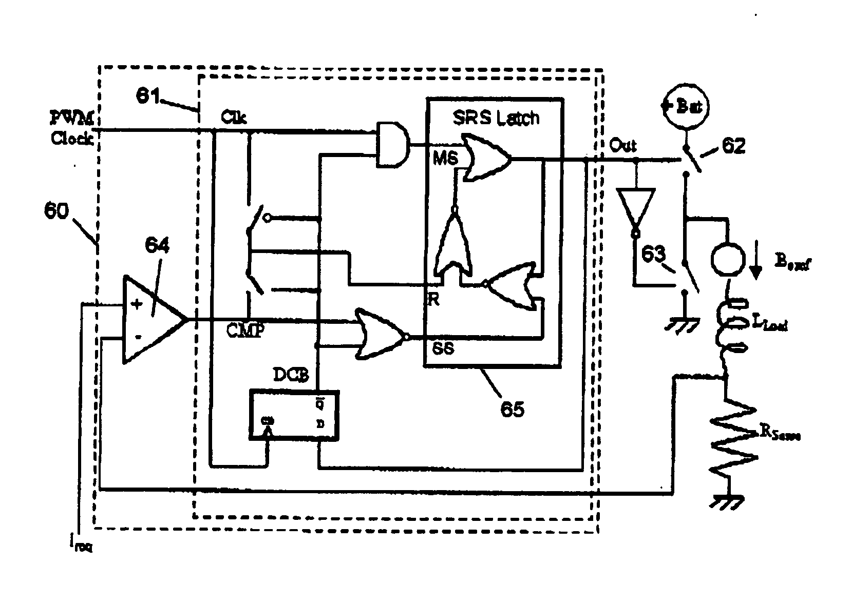
"The present invention provides a controller for a bridge driver circuit that can pulse width modulate control of a current in an inductive load. The controller can switch between a forward mode, a slow decay mode, or a fast decay mode for the duration of pulses at controlled time intervals to provide pulse width modulated control of the current. The controller can also have a selector for selecting top or bottom sense switching, and can detect and compensate for changes in back emf influence on coil-drive. The system includes an integrated circuit incorporating the controller, and a method of controlling a current in an inductive load by switching between a forward mode, a slow decay mode, or a fast decay mode. The technical effects of the invention include a simpler control scheme with lower complexity, a wider range of PWM duty-cycles, and a wider range of output instability."

Problems solved by technology

There are also external components involved, which adds to the cost and complexity.
This can cause audible noise and related human discomfort.
This known device apparently does not use a fast decay mode.
Using mixed decay mode, which requires additional switching points involves increased complexity.
U.S. Pat. No. 4,757,241 is concerned with the problem that PWM systems which regulate CU1Tent have required continuous monitoring of load current to avoid uncontrolled high frequency switching, or have exhibited discontinuity in control output when load current approaches the regulated value, or have not provided for a smooth transition from a current control mode to a voltage control mode.

Method used


Image

  • Control of current in an inductance with pulse width modulation at control frequency
  • Control of current in an inductance with pulse width modulation at control frequency
  • Control of current in an inductance with pulse width modulation at control frequency

Examples


Embodiment Construction

[0041] The present invention will be described with respect to particular embodiments and with reference to certain drawings but the invention is not limited thereto but only by the claims. The drawings described are only schematic and are non-limiting. In the drawings, the size of some of the elements may be exaggerated and not drawn on scale for illustrative purposes.

[0042] The terms first, second, third and the like in the description and in the claims, are used for distinguishing between similar elements and not necessarily for describing a sequential or chronological order. It is to be understood that the terms so used are interchangeable under appropriate circumstances and that the embodiments of the invention described herein are capable of operation in other sequences than described or illustrated herein.

[0043] A useful discussion of PWM control of inductive loads such as motors can be found in “Power Electronics and Variable Frequency Drives”, ed. B. K. Bose, IEEE press, ...


PUM


Abstract

A PWM controller for a bridge driver circuit for controlling current in an inductive load such as a motor, can set the driver into a forward mode, a slow decay mode or a fast decay mode, and can switch from slow decay mode into forward mode or into fast decay mode for the duration of pulses at controlled time intervals to provide pulse width modulated control of the current. This is a simpler control scheme avoiding complex switching schemes related to mixed mode decay. By using a controlled PWM frequency, it is easier to avoid the problems of variable frequency such as increased heat dissipation or acoustic noise generation. It can have a selector for selecting top or bottom sense switching, enabling a wider range of stable PWM duty-cycles to be used (e.g. 0% to 100%), which is useful to compensate for Back emf influence on coil-drive.

Description

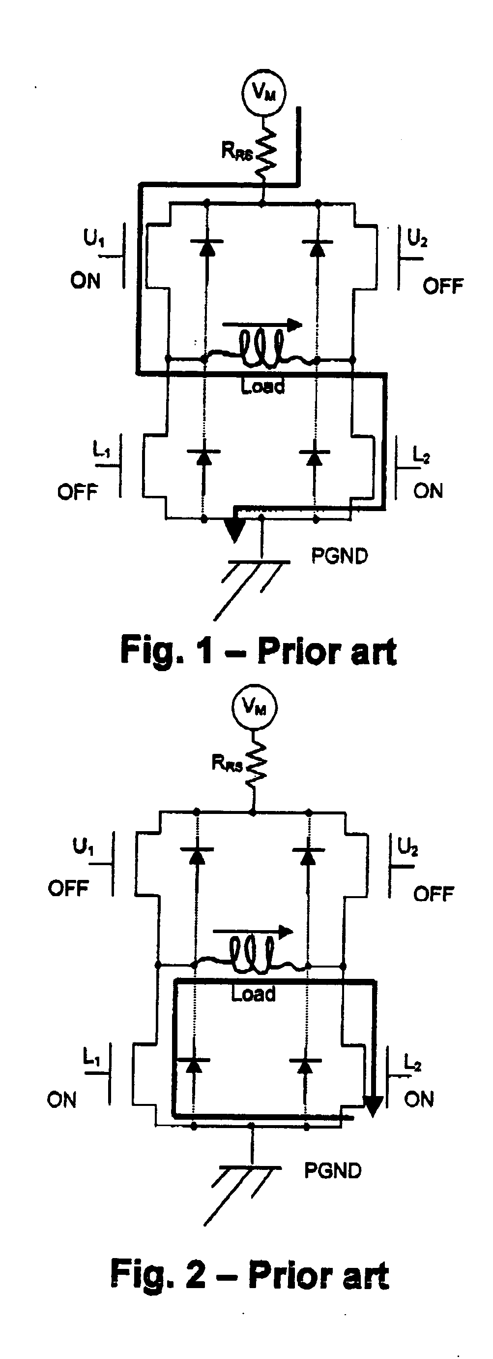
BACKGROUND OF THE INVENTION [0001] 1. The Field of the Invention [0002] This application claims priority under 35 U.S.C. 119 to patent application number 0317629.4 filed in the United Kingdom on Jul. 28, 2003, which is incorporated by reference herein in its entirety. CROSS-REFERENCE TO RELATED APPLICATIONS [0003] This invention relates to controllers for controlling current in an inductive load, to integrated circuits or systems having such controllers) and to corresponding methods. [0004] 2. Background and Relevant Art [0005] It is known to control current in an inductive load (such as a coil, a solenoid and a motor winding) by means of Pulse Width Modulation (PWM) and driver transistors in a full-bridge configuration. Based on measurements of the coil current, a controller executes a decision process to determine when to switch the drivers. A coil current sensor circuit is used to measure the coil current and feed back a measure of the coil current. This value is compared to a re...

Claims


Application Information

Patent Timeline
Patent Type & Authority Applications(United States)
IPC IPC(8): H02M1/00H02M7/521H02M7/538H03B1/00
CPCH02M1/32H02M2003/1555H02M7/53803H02M3/1555
Inventor PLOJHAR, JANCOCK, BART DE
Owner AMI SEMICON BELGIUM
Learn More