
Electric circuit substrate

Inactive Publication Date: 2005-02-24
SONY CORP
View PDF7 Cites 0 Cited by
  • Summary
  • Abstract
  • Description
  • Claims
  • Application Information

AI Technical Summary

Benefits of technology

[0014] It is an object of the present invention to provide an electric circuit substrate having electrodes to which integrated circuit devices (IC) or semiconductor bare chips can be connected with high reliability.
[0018] Accordingly, in the electric circuit substrate according to the present invention, the planarization of the insulating film can be improved. As a result, for instance, when an IC is electrically connected to an electric circuit by attaching integrated circuit devices or semiconductor bare chips from an upper part, an insufficient attachment can be decreased and an attaching operation can be performed with high reliability.

Problems solved by technology

However, a complete planarization is difficult (for instance, a part A3 in FIG. 3).
This step is undesirably more increased.
Accordingly, a deficiency that the pattern of the planarizing films 208 is stripped is undesirably generated (see Japanese Patent Application Laid-Open No. hei 10-161140).

Method used


Image

  • Electric circuit substrate
  • Electric circuit substrate
  • Electric circuit substrate

Examples


Embodiment Construction

[0033] Now, as the best mode for carrying out the present invention, a system display to which the present invention is applied will be described.

[0034]FIG. 4 is a schematic plan view of the system display 10 to which the present invention is applied.

[0035] The system display 10 includes a flat plate shaped glass substrate 11 as a transparent insulating substrate and a liquid crystal display part 12 formed in a rectangular shape at the central part of the glass substrate 11. Further, in the system display 10, to a peripheral edge part of the glass substrate 11 on which the liquid crystal display part 12 is not formed, a power supply cable 13 to which power is supplied and a flexible cable 14 for transmitting and receiving a data signal such as a video signal between an external device and the system display are connected. Further, in the system display 10, to the peripheral edge part of the glass substrate 11 on which the liquid crystal display part 12 is not formed, a power syste...


PUM


Abstract

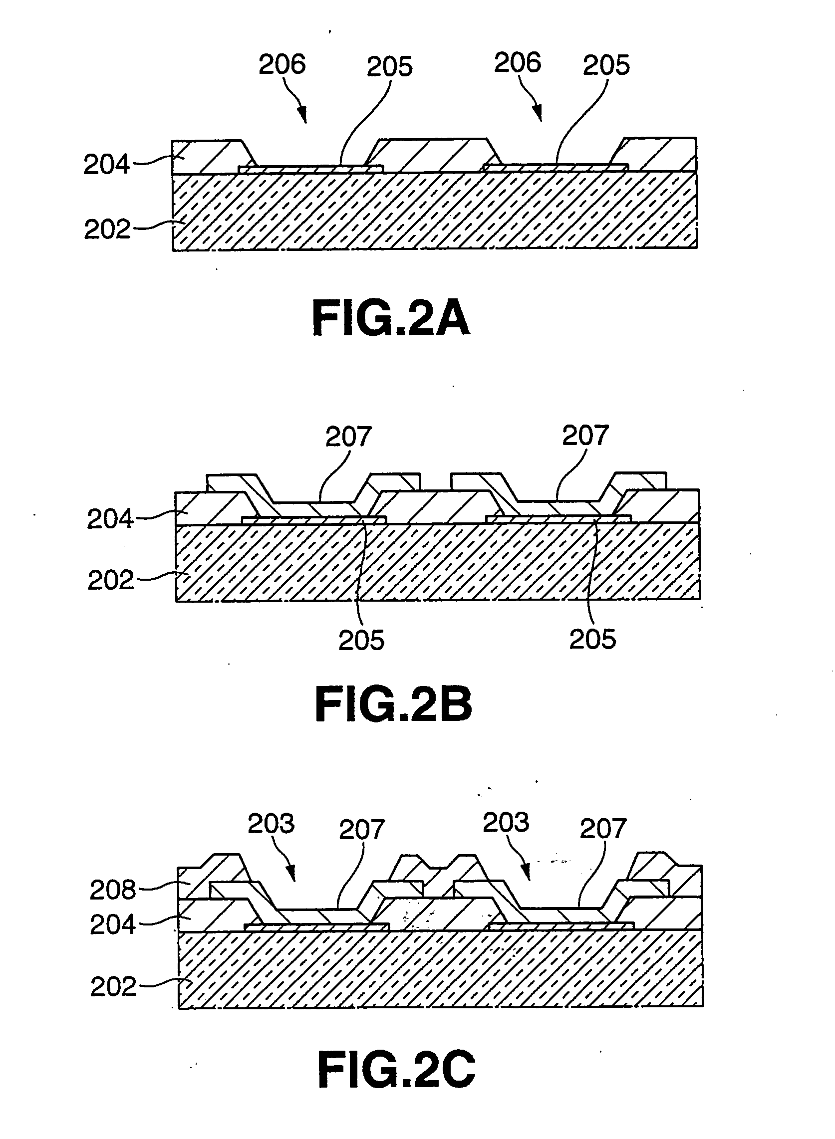
On a glass substrate of a liquid crystal display device, electrode parts to which metallic electrodes (bumps) of an IC circuit are connected from an upper part are formed. The electrode parts are formed by opening an interlayer dielectric film at parts corresponding to metal wiring and forming land shaped electrode pads in the opening parts. In this invention, the planar forms of the electrode pads are smaller than the opening parts of the interlayer dielectric film. Thus, the planarization of the peripheral surfaces around the electrode parts is improved. Accordingly, integrated circuit devices (IC) or semiconductor chips can be connected with high reliability.

Description

BACKGROUND OF THE INVENTION [0001] 1. Field of the Invention [0002] The present invention relates to an electric circuit substrate having an electrode part to which integrated circuit devices (IC) or semiconductor bare chips are connected. [0003] This application claims priority of Japanese Patent Application No. 2003-299266, filed on Aug. 22, 2003, the entirety of which is incorporated by reference herein. [0004] 2. Description of the Related Art [0005] In recent years, in order to achieve the miniaturization of a liquid crystal display device, integrated circuit devices (IC) or semiconductor bare chips serving as a driving circuit, a peripheral circuit or the like are directly attached to a peripheral edge part of a glass substrate on which a liquid crystal display part is formed. [0006] For instance, when an IC 101 is directly attached to a peripheral edge part of a glass substrate 202 around a liquid crystal display part 201, as shown in FIG. 1A, protrusion shaped bumps 102 serv...

Claims


Application Information

Patent Timeline
IPC IPC(8): G02F1/13G02F1/1343G02F1/1345G09F9/00G09F9/30H01L21/60H01L23/498H05K1/03H05K3/40
CPCG02F1/13452H01L2924/01006H01L23/49822H01L24/81H01L24/83H01L2224/16H01L2224/81801H01L2224/83192H01L2224/838H01L2924/01005H01L2924/01013H01L2924/01029H01L2924/01033H01L2924/01042H01L2924/0106H01L2924/0781H01L2924/14H01L2924/3011H05K1/0306H05K3/4007H05K2201/0367H05K2201/099H05K2201/10674H05K2203/1189H01L24/29H01L23/49816G02F1/1345
Inventor TORIYAMA, SHIGETAKA
Owner SONY CORP
Learn More