Apparatus for generating virtually pure hydrogen for fuel cells

Inactive Publication Date: 2005-02-24
DAIMLER AG
View PDF7 Cites 3 Cited by
  • Summary
  • Abstract
  • Description
  • Claims
  • Application Information

AI Technical Summary

Benefits of technology

[0008] An object of the present invention is to provide an apparatus for generating virtually pure hydrogen for fuel cells which avoids the abovementioned drawbacks and, while taking up a minimal amount of space and entailing the lowest possible costs, makes it possible to provide a large quantity of virtually pure hydrogen per unit volume of the starting substances used.
[0016] The catalytic means for producing a water gas shift reaction are now partially arranged in the device for separating off hydrogen and partially in the device for exchanging thermal energy. A temperature level which is suitable for the water gas shift reaction prevails both in the hydrogen-separating device and in—at least the exit-side part of—the device for exchanging thermal energy, and consequently with a structure of this nature it is possible to obtain very favorable conditions for the water gas shift reaction.
[0017] The apparatus according to the present invention particularly advantageously allows the space for an independent water gas shift stage which is required in conventional structures to be saved. The apparatus according to the invention has two crucial advantages over the use of a pure membrane reactor. The use of the device for exchanging thermal energy creates the possibility of operating the device for reforming the starting substances at a correspondingly high temperature. This results in a high degree of variation in the operation conditions of the device for reforming the starting substances without its exit temperature necessarily having to be suitable for a water gas shift reaction or the permeation of hydrogen in the hydrogen-separating device. This is because the device for exchanging thermal energy, despite the high variability and high temperature, and therefore correspondingly high yields of hydrogen from the region of the reforming device, nevertheless allows a suitable temperature level for the water gas shift reaction, on the one hand, and the permeation of the hydrogen, on the other hand to be obtained.
[0018] A further advantage is the division of the catalytic agent required in order to produce a water gas shift reaction between at least a part of the device for exchanging thermal energy and the hydrogen-separating device. Compared to the pure membrane reactor, which includes all the catalytic agent required to produce a water gas shift reaction in the region of the hydrogen-separating device, this gives the advantage that the hydrogen-separating device can be significantly smaller and therefore need only have the surface area of membranes which are selectively permeable to hydrogen that is absolutely imperative in order to produce the desired quantity of hydrogen. Since the materials which are selectively highly permeable to hydrogen, such as for example Pd and / or elements belonging to transition group 5 and alloys thereof are relatively expensive, in addition to the simple saving on space in the hydrogen-separating device, it is at the same time possible also to achieve a significant saving in terms of materials costs.
[0020] Therefore, the apparatus according to the present invention provides a very simple, expedient, efficient and highly compact apparatus for generating virtually pure hydrogen for fuel cells.

Problems solved by technology

Now, the drawback of membrane reactors of this type is that the materials which are currently available, such as for example Pd, etc., for the production of the hydrogen-selective membranes, although highly selective under appropriate operating conditions, are relatively expensive.
On account of the high selective permeability which can be achieved, however, the overall space available in the reformate-gas-side entry region then becomes so small that the catalyst for producing the water gas shift reaction can no longer be accommodated in sufficient quantities in the membrane reactor.
Moreover, the catalyst may disadvantageously be overheated by the hot reformate flowing out of the reformer.
This may both damage the catalyst and interfere with the water gas shift reaction.

Method used


Image

  • Apparatus for generating virtually pure hydrogen for fuel cells
  • Apparatus for generating virtually pure hydrogen for fuel cells

Examples


Embodiment Construction

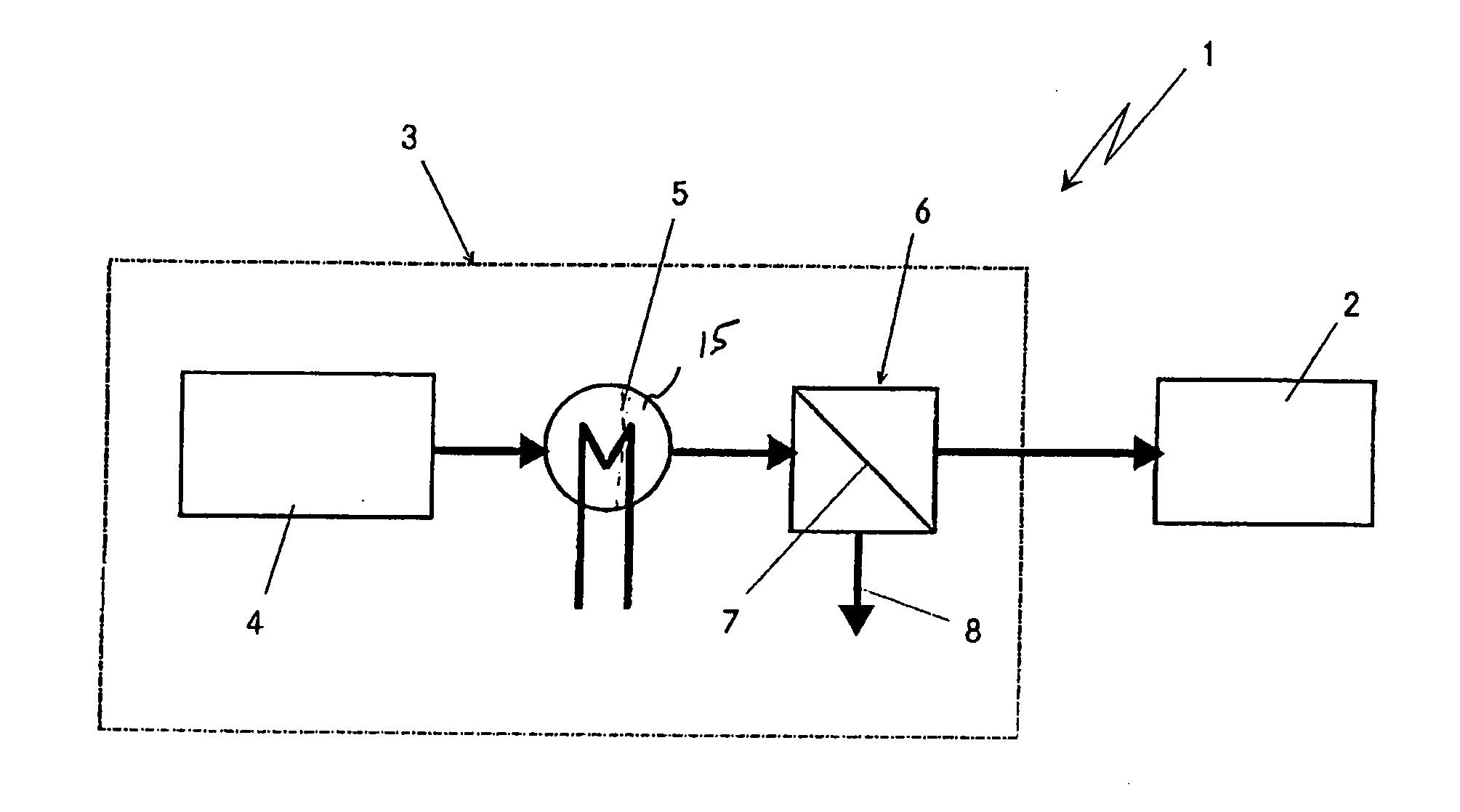
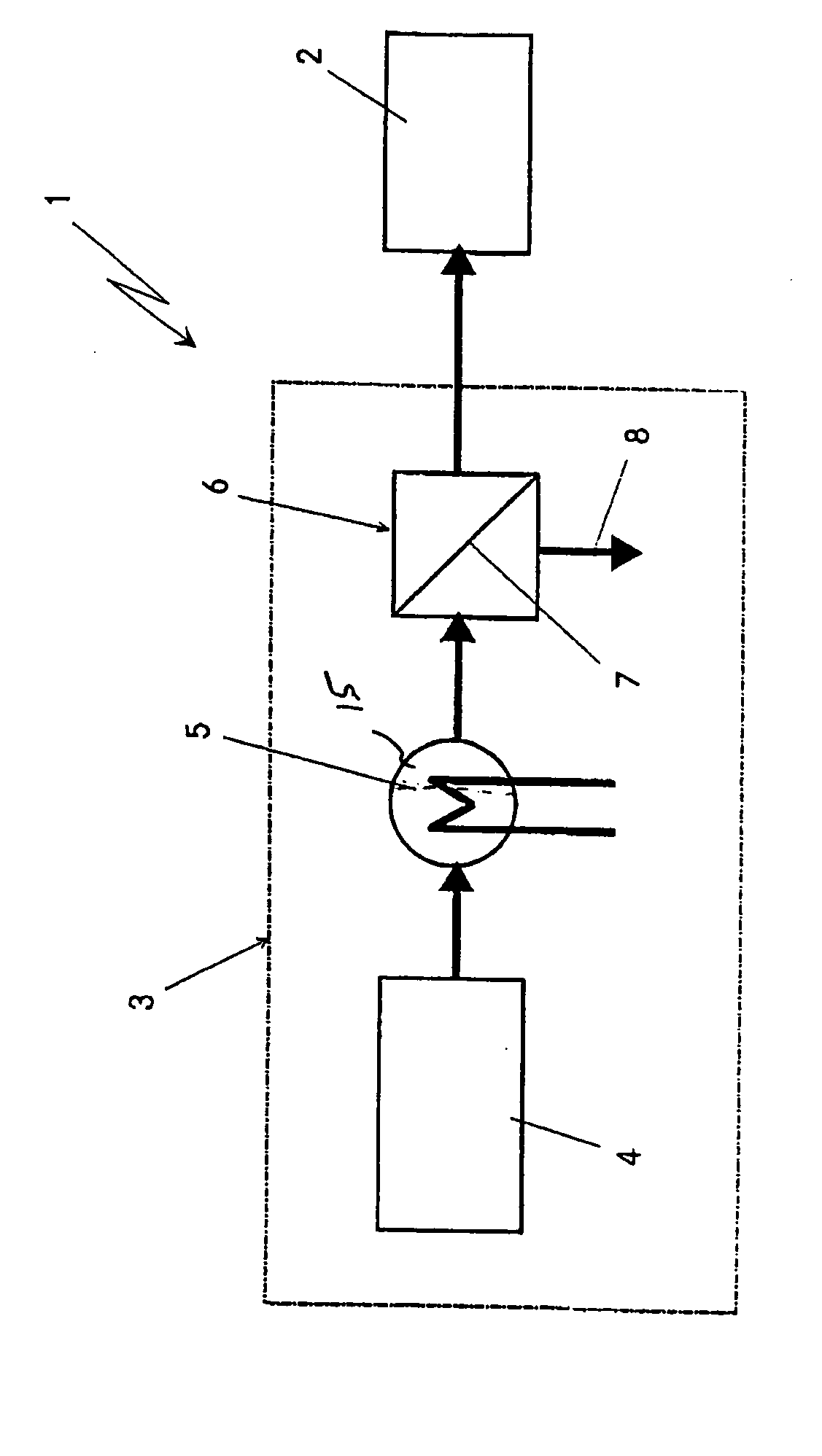
[0025] The fuel cell system 1 which is highly diagrammatically depicted in the only appended figure comprises a fuel cell stack 2, in particular based on a plurality of PEM fuel cells. Furthermore, the fuel cell system 1 comprises a highly diagrammatically depicted apparatus 3 for generating virtually pure hydrogen for operating the fuel cell stack 2. The apparatus 3 is subdivided into three main components, once again highly diagrammatically depicted.

[0026] The first component is a device 4 for reforming starting substances, which may be designed, for example, as an autothermal reformer or as a steam reformer. According to the exemplary embodiment illustrated here, this reformer 4, starting from a liquid hydrocarbon or hydrocarbon derivative, in particular petrol, diesel or methanol, together with water and if appropriate air as further starting substances, will generate a hydrogen-containing gas. Depending on the type of reforming, this hydrogen-containing reformate gas will leav...


PUM


Abstract

An apparatus generates virtually pure hydrogen for fuel cells, and includes a device for reforming starting substances having at least one hydrocarbon-containing compound and water. Furthermore, the apparatus has catalytic agents for producing a water gas shift reaction in the reformate gas stream generated by the reforming device. Moreover, the apparatus includes a device for separating hydrogen out of the reformate gas stream using membranes which are selectively permeable to hydrogen. The hydrogen-separating device includes a proportion of the catalytic agents for producing the water gas shift reaction. A device for exchanging thermal energy between the reformate gas stream and a further stream of medium is arranged downstream, as seen in the direction of flow, of the reforming device. The device for exchanging thermal energy includes a further proportion of the catalytic agents for producing the water gas shift reaction.

Description

[0001] Priority is claimed to German Patent Application DE 103 37 014.5, filed Aug. 12, 2003, and German Patent Application DE 103 40 173.3, filed Sep. 1, 2003, the entire disclosures of which are incorporated by reference herein. BACKGROUND [0002] The present invention relates to an apparatus for generating virtually pure hydrogen for fuel cells. [0003] An apparatus of the generic type is described by Japanese Patent Application 2002068710 A. The apparatus has a reformer and a membrane module with membranes that are selectively permeable to hydrogen. In its entry space for the reformate gas, the membrane module has a catalyst for producing a water gas shift reaction, producing what is known as a membrane reactor. [0004] A membrane reactor of this type offers the option of integrating the water gas shift reaction into the entry space of the membrane module. A similar structure is also described by U.S. Pat. No. 5,525,322. [0005] Now, the drawback of membrane reactors of this type is...

Claims


Application Information

Patent Timeline
IPC IPC(8): C01B3/38B01J8/00B01J12/00B01J19/24C01B3/48C01B3/50C01B3/56H01M8/00H01M8/04H01M8/06
CPCB01J8/009Y02T90/32B01J19/2475B01J19/249B01J2208/00973B01J2219/2453B01J2219/2458B01J2219/2465B01J2219/2475B01J2219/2479B01J2219/2485C01B3/48C01B3/501C01B2203/0233C01B2203/0283C01B2203/0405C01B2203/0475C01B2203/0883H01M8/0612H01M8/0631H01M8/0687H01M2250/20Y02E60/50B01J12/007Y02T90/40
Inventor LAMM, ARNOLDPOSCHMANN, THOMASSCHAEFER, JOCHEN
Owner DAIMLER AG
Why Eureka
Try Eureka