Distributed configuration storage

a configuration storage and distribution technology, applied in computing, instruments, electric digital data processing, etc., can solve the problems of logic design errors in interpreting configuration register specifications, excessive routing resources, layout and timing problems, etc., to improve layout efficiency and logic design accuracy

Inactive Publication Date: 2005-02-17
ROUND ROCK RES LLC
View PDF15 Cites 6 Cited by
  • Summary
  • Abstract
  • Description
  • Claims
  • Application Information

AI Technical Summary

Benefits of technology

[0011] It is an object of this invention to improve the layout efficiency and logic design accuracy of providing configuration storage in devices.
[0014] Each target module includes a DCON bus interface and at least one storage array. A storage array includes one or more registers associated with the design section that the storage array resides in. More than one storage array may be associated with the design section. In addition, a configuration register may be shared by more than one design section or device. Each register bit in the storage array can be configured as one of several different register classifications. The DCON bus interface translates the DCON bus commands into signals that access one of the registers in one of the storage arrays. Configuration data from the storage array can then be sent out of the target module through an output port via a CONFIG bus for use by the surrounding design section. The invention improves the efficiency of place-and-route tools by reducing the number of wires that interconnect design sections (e.g., by using a DCON bus). In addition, because the configuration registers reside locally in each design section, the length of the CONFIG bus connections are reduced, and configuration data is provided to the surrounding design section more efficiently.
[0015] Advantageously, the creation of each storage array in the distributed configuration storage can be automated. The specifications for each register bit in each storage array can be presented in tabular form, such as, for example, in a Microsoft Word document. This tabular form can then be compiled using, for example, a Visual Basic script tool that automatically converts the tabular form to an HDL code, such as, for example, VHDL code. Automating the creation of each storage array reduces the potential problem of having unconnected inputs and outputs related to unused storage bits. Unused bits are automatically logically tied to a binary value rather than being stored in a clock-based register such as a flip-flop. In addition, test codes can also be automatically generated for test pattern simulation of a computer system by testing each register bit, and the interconnections to and from each register bit, in configuration storage.

Problems solved by technology

Global routing resources are then needed to route each configuration bit to the design section in which they are used, resulting in excessive routing resources.
This can cause layout and timing problems in programmable logic device (PLD) designs, application-specific integrated circuit (ASIC) designs, and field-programmable gate array (FPGA) designs.
This can be a laborious process that can lead to logic design errors in interpreting the configuration register specifications.
Also, configuration registers not used in a device can have unconnected inputs and outputs that can lead to problems with place-and-route tools.
Furthermore, test code for simulating test patterns in configuration storage is also manually created, thus also prone to errors.

Method used


Image

  • Distributed configuration storage
  • Distributed configuration storage
  • Distributed configuration storage

Examples


Embodiment Construction

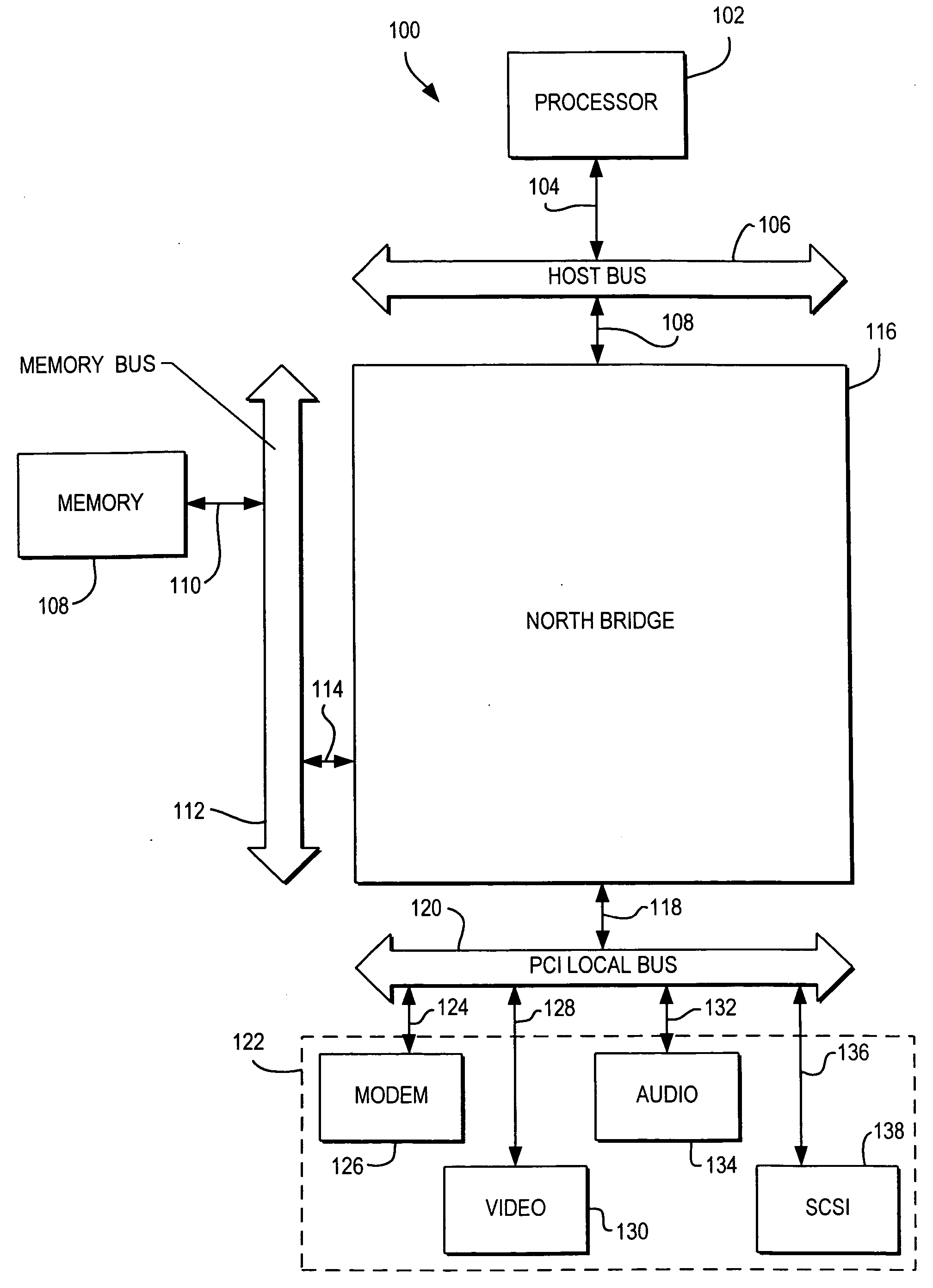
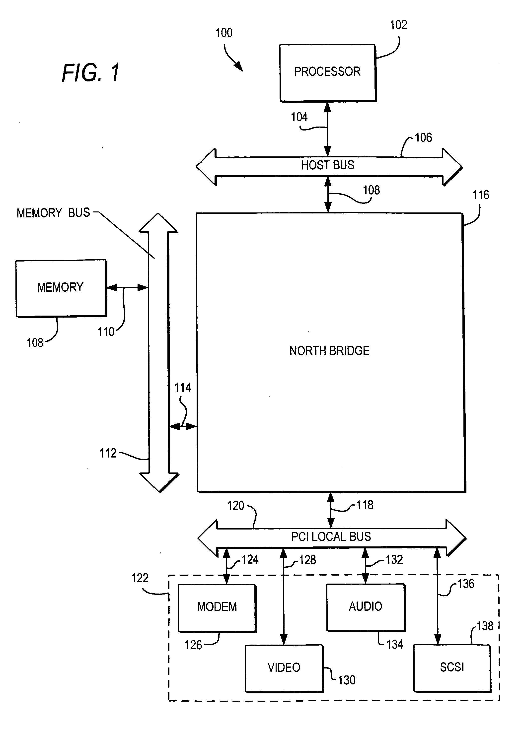
[0026] The invention is directed to systems and methods that provide distributed configuration storage within a device. Devices in a computer system that have configuration storage include, for example, peripheral devices compatible with bus system architectures such as Industry Standard Architecture (ISA), Extended ISA (EISA), and Peripheral Component Interconnect (PCI); a memory-mapped input-output (I / O) space; and any addressable register block (e.g., central processing unit registers). Although the invention applies to any suitable device having configuration storage, the invention is herein described for clarity primarily in the context of configuration storage in PCI compatible devices that conform to a PCI bus architecture.

[0027]FIG. 1 shows a computer system 100 employing PCI bus architecture. Computer system 100 includes a processor 102, a memory 108, peripheral devices 122, and a chipset 116 (chipset 116 and peripheral devices 122 are herein collectively referred to as PC...


PUM


Abstract

Systems and methods, for providing distributed configuration storage are presented. The configuration storage is divided into distributed configuration target modules that are physically located in each design section of a device that uses configuration storage. A distributed configuration master module, physically located near the host interface, controls access into and out of each target module via a distributed configuration bus. The creation of each storage array in the distributed configuration storage can be automated using a scripting tool that converts each register specification into hardware description language code.

Description

BACKGROUND OF THE INVENTION [0001] This invention relates to computer systems. More particularly, this invention relates to computer systems having configuration storage. [0002] A computer system typically includes a processor, a memory, and a plurality of peripheral devices. These peripheral devices include, for example, keyboards, mice, display monitors, storage devices such as hard disk drives and compact-disk read-only-memories (CD-ROMs), printers, video cards, audio cards, modems, small computer system interfaces (SCSIs), universal serial buses (USBs), memory controllers, and other chips or chipsets. These peripheral devices are typically connected to one or more buses that allow the peripheral devices to interface with the system processor and memory to perform certain functions. [0003] A computer system typically employs at least one bus system architecture for interfacing the peripheral devices with the system processor and memory. Such bus system architectures include, for ...

Claims


Application Information

Patent Timeline
Patent Type & Authority Applications(United States)
IPC IPC(8): G06F3/00G06F17/50
CPCG06F17/5045G06F30/30
Inventor MEYER, JAMES W.KLIER, JAKE
Owner ROUND ROCK RES LLC
Why Eureka
Try Eureka