
Methods and apparatus for ink delivery to nanolithographic probe systems

Inactive Publication Date: 2005-02-17
NANOINK INC
View PDF5 Cites 149 Cited by
  • Summary
  • Abstract
  • Description
  • Claims
  • Application Information

AI Technical Summary

Benefits of technology

Recent advances have been made wherein tips are used to apply inks to surfaces at both the microscopic and nanoscopic scale. For example, tips can be non-hollow and coated with the ink on the tip surface before application of the ink to the surface. Alternatively, tips can be hollow and the ink can pass through the hollow region of the tip to the surface. The result is excellent molecular level control of a printing process. In many cases, the tips or nanoscopic tips and can be used for both ink transfer and for imaging of patterns by scanning probe microscopic methods including atomic force microscopic methods. Physical and chemical interactions between the ink and the surface can be used to engineer the printed structure. Moreover, the meniscus between a nanoscopic tip and the surface can be used to facilitate printing. The processes can be adapted for single tips or multiple tips using single inks or multiple inks. Alignment can be excellent. However, many technical challenges arise with these printing processes at small scale, including the nanoscale, which do not arise with larger scale printing.
Basic and novel features of the invention include adapting features of inkwells, including microfluidic inkwells, for direct-write nanolithographic printing with use of tips and generally avoiding features undesirable or extraneous to nanolithographic printing.

Problems solved by technology

However, many technical challenges arise with these printing processes at small scale, including the nanoscale, which do not arise with larger scale printing.
Existing commercial products do not allow for this advanced ink delivery and, generally, little is known about commercial use of ink wells and microfluidics for nanolithographic printing.
Moreover, they are not adapted for use with instruments and printing equipment, particularly at the commercial scale.

Method used


Image

  • Methods and apparatus for ink delivery to nanolithographic probe systems
  • Methods and apparatus for ink delivery to nanolithographic probe systems
  • Methods and apparatus for ink delivery to nanolithographic probe systems

Examples


first embodiment

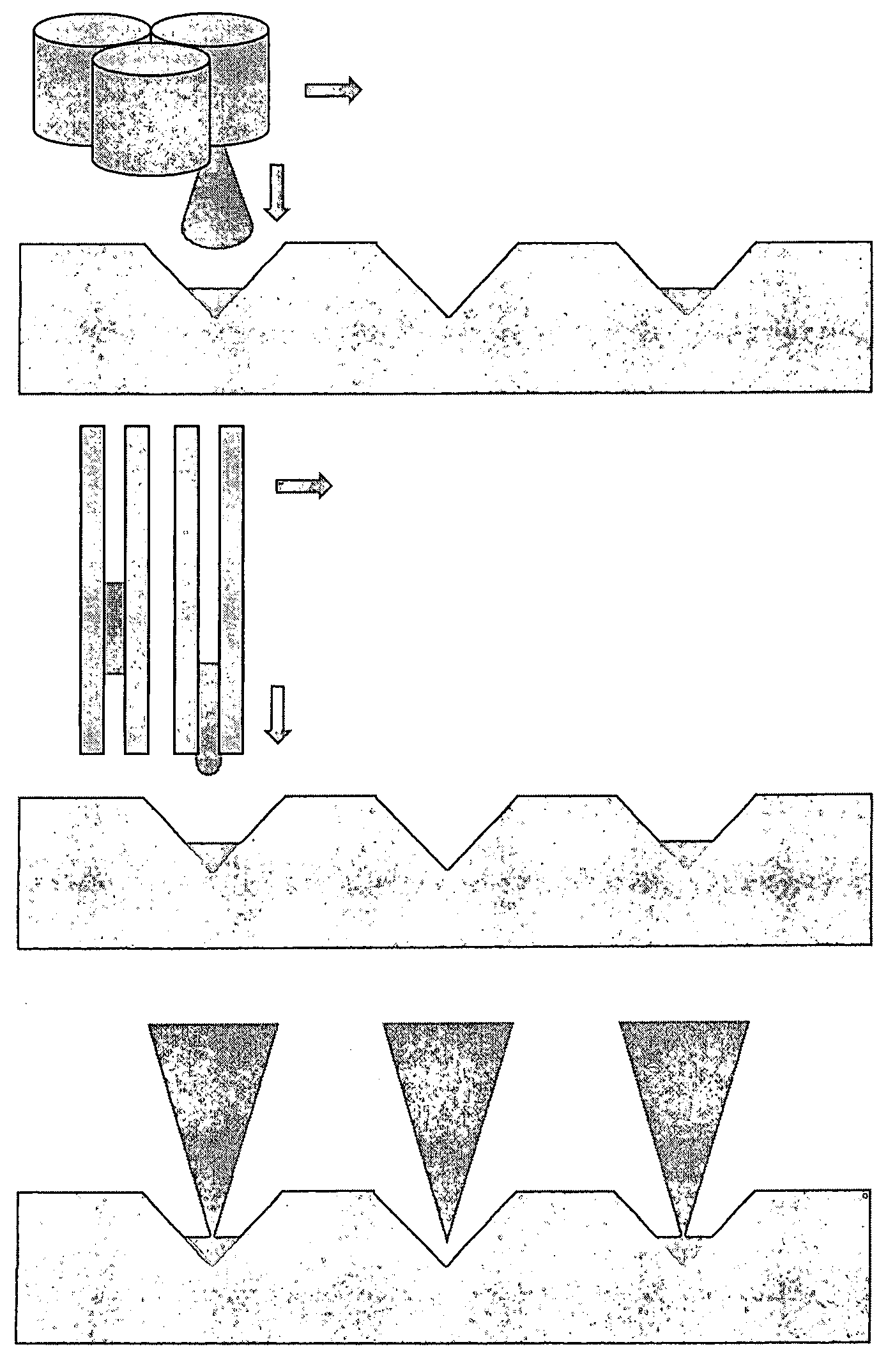
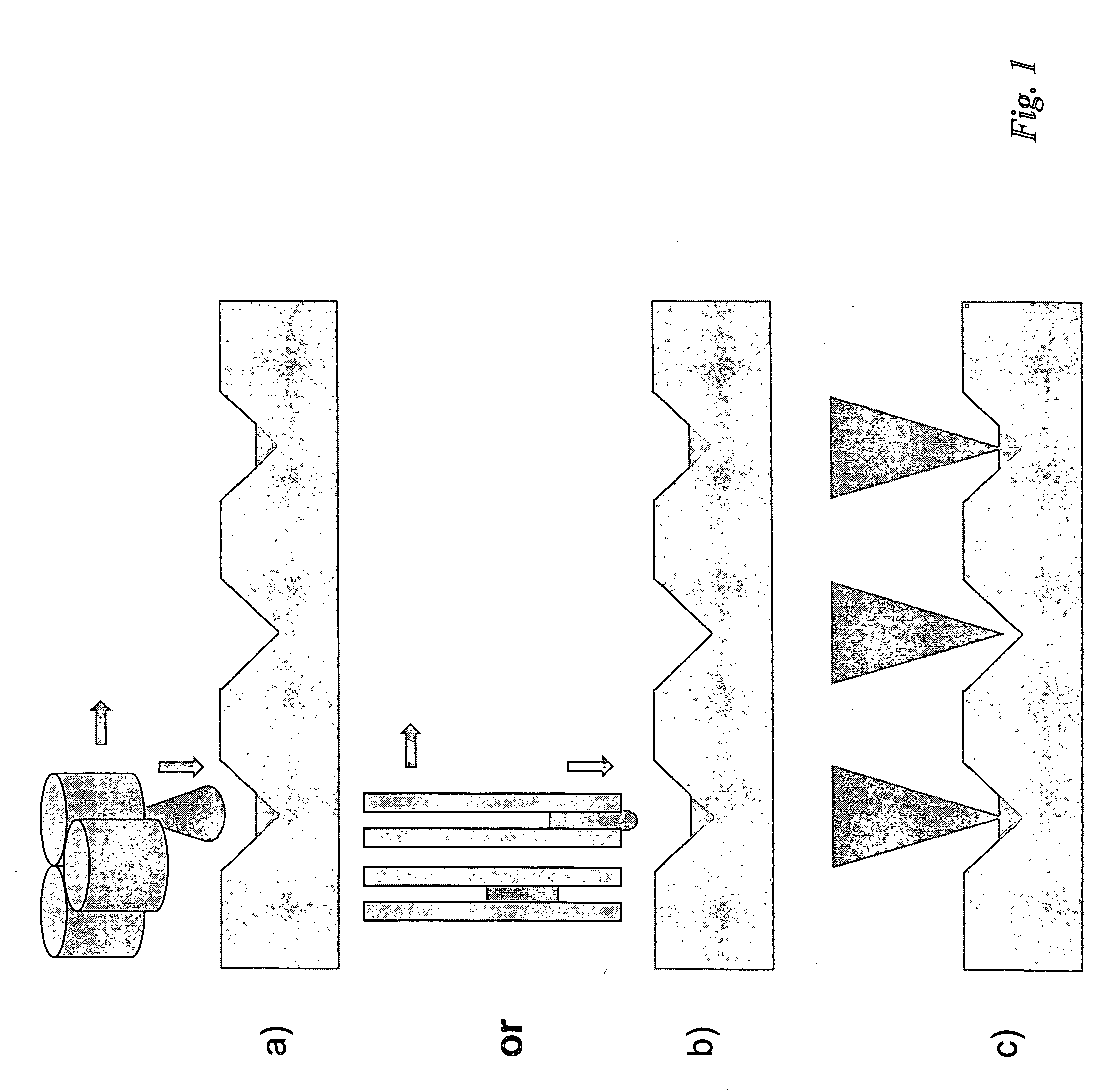
In a first embodiment, a rolling cylinder or sphere may be brought in close proximity with the probe array to ink, and (groups of) probe(s) may be contacted with the cylinder. The cylinder may be inked by microfludics circuits connected with ink reservoirs or may be patterned e.g., by rolling the cylinder on an inked microcontact printing stamp.

second embodiment

A second embodiment may be comprised of a device similar to a dot matrix printer head or a pin-and-ring microspotter. Spring-loaded pins terminated by a cusp or a spongy tip (acting as an ink reservoir) may be electromechanically actuated. The pin assembly may be brought in close contact with the probe assembly, so that ink may be delivered by mechanical contact between the pin head and a probe.

In the pin-and-ring design, a ring is dipped in an initial ink reservoir (e.g., microtiter plates) and stores some of the fluid to be delivered by capillary action. The pin is then coated with ink by plunging it through a fluid disc.

third embodiment

A third embodiment may use another inked probe, a probe array, or a series of probe arrays to ink the probe or probe array to be used in the nanolithographic apparatus.

Non-Contact (Inkjet) Delivery

In this embodiment of the invention, the probe or probe assembly to be inked may be brought in proximity of a dispensing system that releases a controlled amount of fluid in the form, for example, of an ink droplet, bubble or (exceptionally) of a powdered aggregate. The ink droplet(s) may be directed towards the tip or an associated structure, from which the ink may be transported to the tip.

The dispensing system may include one or more fluid dispensing nozzles, operating with one or more inks (FIG. 7). Dispensing by the fluid nozzle may be driven by a mechanical actuator, such as a piezoelectric ceramic, an electrorheologic constrictive device, a solenoid plunger, or an actuated membrane [Lemmo, Rose, Tisone Cur. Opinion Biotech. 9, 615 (1998)]. Among other possible appropriate means...


PUM


Abstract

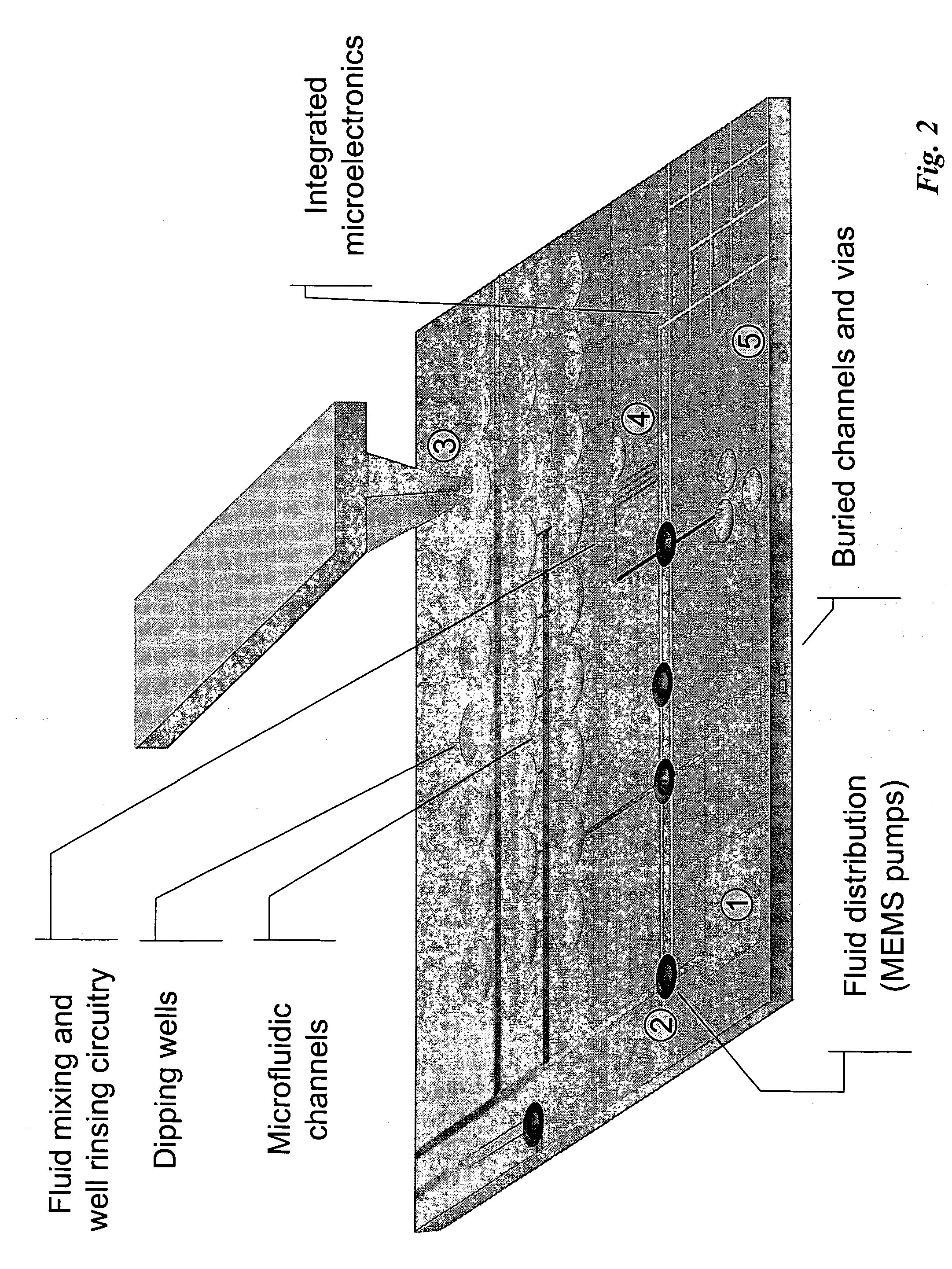
Inkwells adapted for use in direct-write nanolithography and other applications including use of wells, channels, and posts. The wells can possess a geometry which matches the geometry of tips which are dipped into the inkwells. The channels can be open or closed. Hydrophilicity and hydrophobicity can be used to control ink flow. SEM can be used to characterize the inkwells. Ink flow can be monitored with video. Hydrophobic material layers can be used to prevent cross contamination. Microsyringes can be used to fill reservoirs. Satellite reservoirs can be used to prevent bubble formation.

Description

INTRODUCTION Recent advances have been made wherein tips are used to apply inks to surfaces at both the microscopic and nanoscopic scale. For example, tips can be non-hollow and coated with the ink on the tip surface before application of the ink to the surface. Alternatively, tips can be hollow and the ink can pass through the hollow region of the tip to the surface. The result is excellent molecular level control of a printing process. In many cases, the tips or nanoscopic tips and can be used for both ink transfer and for imaging of patterns by scanning probe microscopic methods including atomic force microscopic methods. Physical and chemical interactions between the ink and the surface can be used to engineer the printed structure. Moreover, the meniscus between a nanoscopic tip and the surface can be used to facilitate printing. The processes can be adapted for single tips or multiple tips using single inks or multiple inks. Alignment can be excellent. However, many technical...

Claims


Application Information

Patent Timeline
IPC IPC(8): B05C1/00B05D5/00B43L25/00G01D15/16G01NG03F7/00
CPCB82Y10/00G03F7/0002B82Y40/00B82Y30/00
Inventor CRUCHON-DUPEYRAT, SYLVAINNELSON, MICHAELELGHANIAN, ROBERTFRAGALA, JOSEPH S.TOUZOV, IGORBANERJEE, DEBJYOTI
Owner NANOINK INC
Learn More