
Forming apparatus and method

Active Publication Date: 2005-02-17
THE BOEING CO
View PDF18 Cites 167 Cited by
  • Summary
  • Abstract
  • Description
  • Claims
  • Application Information

AI Technical Summary

Benefits of technology

[0008] The present invention provides an apparatus and method for forming a composite workpiece to a desired configuration in a die cavity. An electromagnetic field generator induces a current in a susceptor, thereby heating the workpiece, and an elastomeric bladder in the die cavity urges the workpiece against a contour surface corresponding to the desired configuration. The workpiece can be heated quickly to a forming temperature without heating large supporting tool members in the die cavity. Further, coolant fluid can be supplied to the die cavity to cool the workpiece quickly or in an otherwise controlled manner. Thus, the time and energy required for forming the workpiece is reduced.

Problems solved by technology

This method is generally time consuming, and often results in wasted materials such as the plaster mandrel.
The time and energy required for heating and cooling the tools adds to the expense of the manufacturing process.

Method used


Image

  • Forming apparatus and method
  • Forming apparatus and method
  • Forming apparatus and method

Examples


Embodiment Construction

[0025] The present invention now will be described more fully hereinafter with reference to the accompanying drawings, in which some, but not all embodiments of the invention are shown. Indeed, this invention may be embodied in many different forms and should not be construed as limited to the embodiments set forth herein; rather, these embodiments are provided so that this disclosure will satisfy applicable legal requirements. Like numbers refer to like elements throughout.

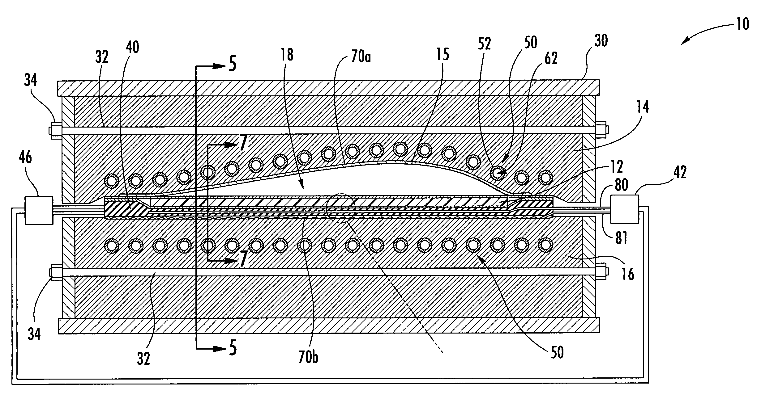
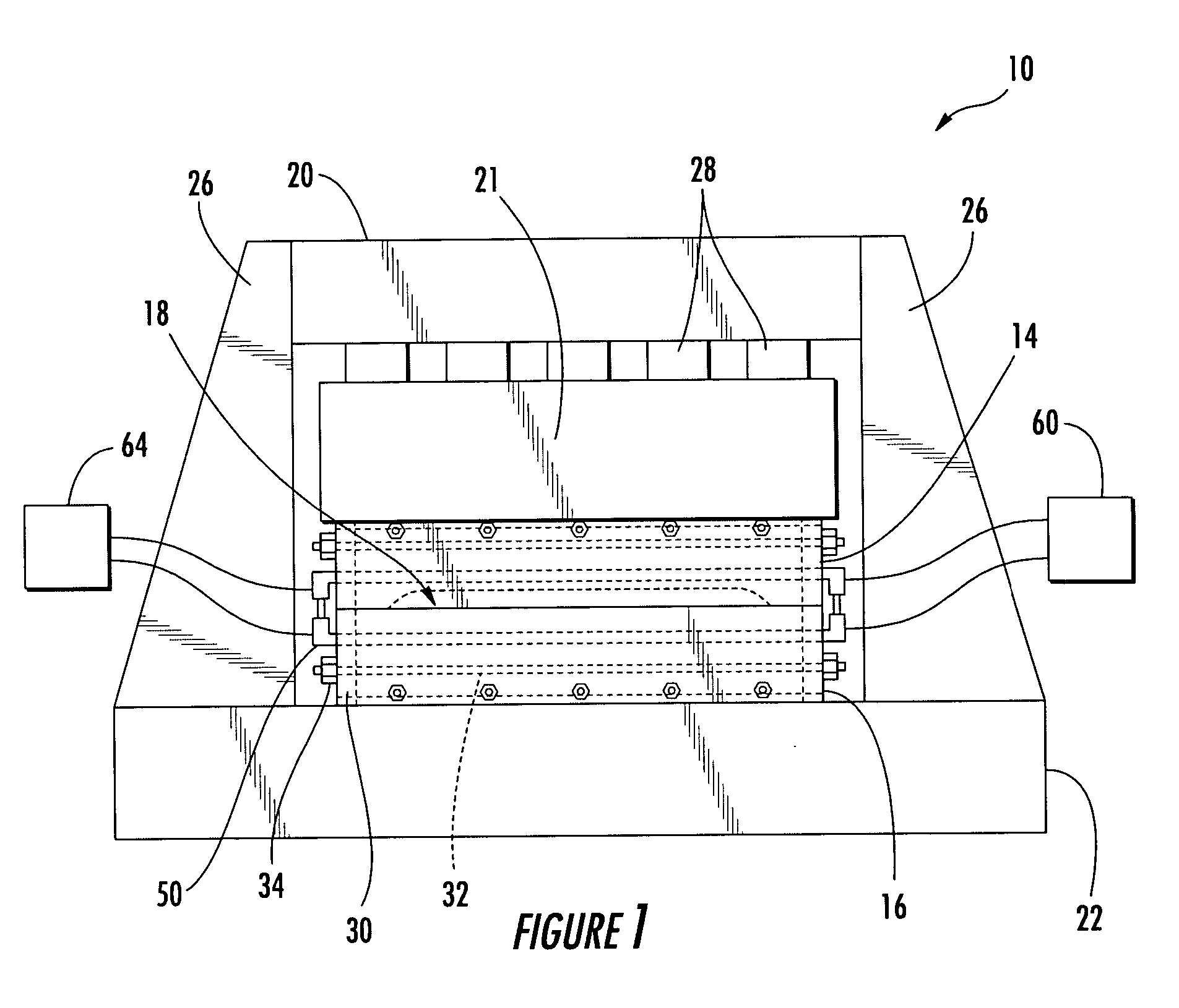
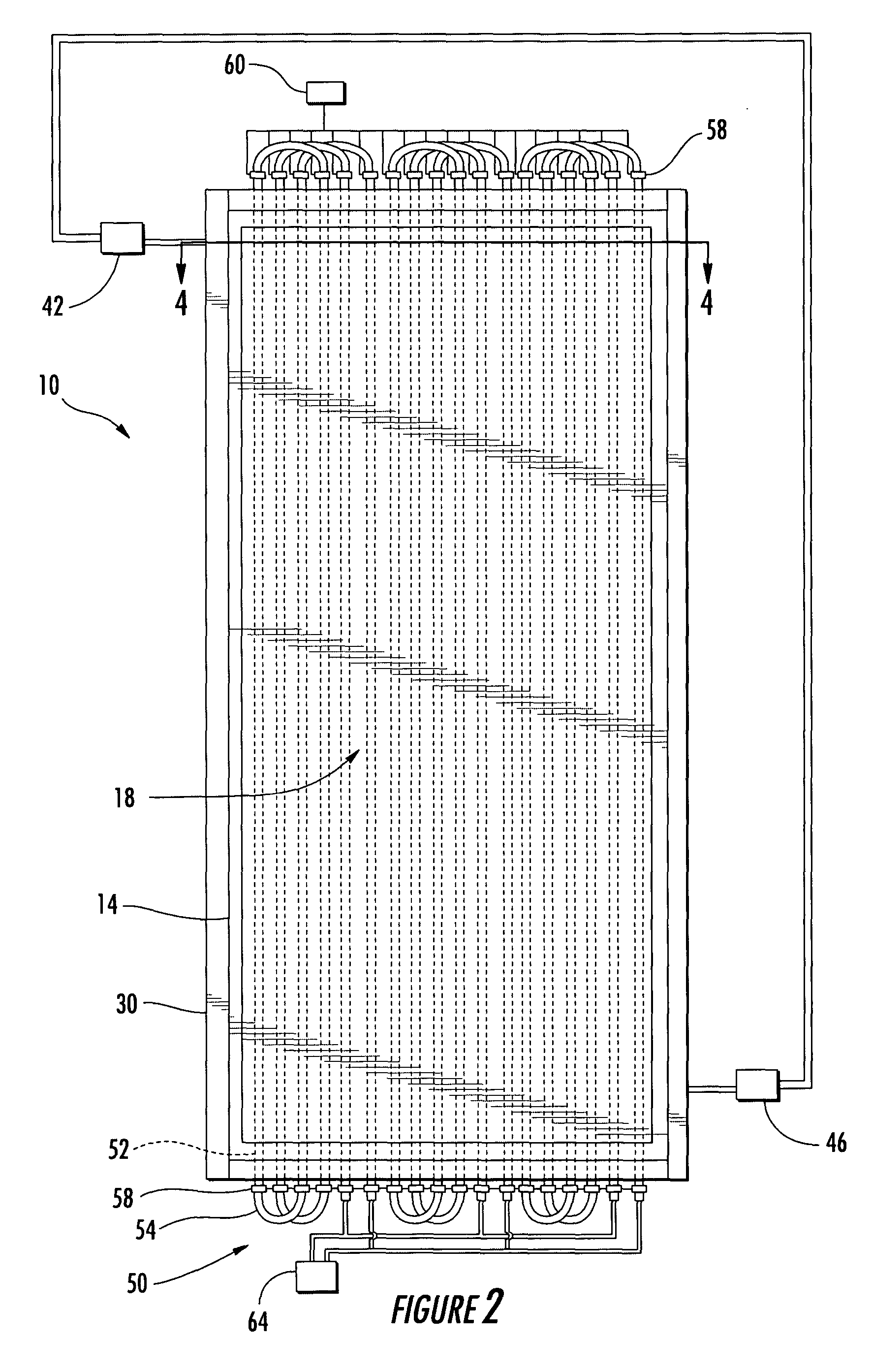
[0026] Referring now to the drawings, and in particular to FIGS. 1 and 2, there is illustrated a forming apparatus 10, according to one embodiment of the present invention. The apparatus 10 can be used to form a composite workpiece 12 (FIG. 3) including a fibrous material and a matrix material to a desired configuration. For example, workpiece blanks that are substantially flat can be formed to a predetermined configuration of a curved, bent, or otherwise contoured panel or structure.

[0027] The apparatus 10 inc...


PUM

PropertyMeasurementUnit
Temperatureaaaaaaaaaa
Timeaaaaaaaaaa

Abstract

An apparatus and method for forming a composite workpiece are provided. An electromagnetic field generator induces a current in a susceptor, thereby heating the workpiece in a die cavity. An elastomeric bladder in the cavity is inflated and urges the workpiece against a contour surface corresponding to a desired configuration of the workpiece. Coolant fluid can also be circulated through the die cavity to cool the workpiece. Thus, the workpiece can be heated, formed, and cooled quickly and without substantial heating of other components, thereby reducing the time and energy relative to conventional forming methods.

Description

BACKGROUND OF THE INVENTION [0001] 1) Field of the Invention [0002] The present invention relates to composite materials and, more particularly, relates to the forming of a composite workpiece by inductively heating the workpiece and applying pressure thereto. [0003] 2) Description of Related Art [0004] Composite materials typically include a fibrous material such as graphite that is impregnated with a matrix material. The fibrous material is generally strong and stiff and is held in place by the matrix material, which can be formed of a thermoplastic resin, a thermoset resin, or a metal. In combination, the fiber and matrix can provide a strong, stiff, lightweight material, which can also have specific dimensional properties. Examples of composite materials include alumina-, boron-, or silicon carbide-based fibers provided in a weave, braid, or non-woven arrangement and combined with a matrix formed of Ultem® polyetherimide (PEI) resin, a registered trademark of General Electric Co...

Claims


Application Information

Patent Timeline
IPC IPC(8): B29C33/04B29C33/06B29C35/08B29C35/16B29C70/44B29C70/54H05B6/02H05B6/14
CPCB29C33/04B29C33/046B29C33/06B29C35/0805H05B2206/023B29C70/54B29C2035/0811B29C2035/1616H05B6/105B29C70/44B29C2035/0816
Inventor ANDERSON, DONALD A.BROWN, RONALD W.KIRKWOOD, BRAD L.MATSEN, MARC R.MCCARVILLE, DOUGLAS A.MOORE, STEPHEN G.
Owner THE BOEING CO
Learn More