
Apparatus, system and method to facilitate reconfigurable welding power supply

a technology of reconfigurable welding and equipment, applied in the field of computer and welding systems, can solve the problems of increasing control, maintenance and servicing multiple and isolated locations in large centers and/or across the globe, time-consuming and expensive, and process to stop or be disrupted, so as to facilitate troubleshooting, service, operation, maintenance and/or upgrading, and facilitate the delivery rate of consumable wires. , the effect of facilitating communication

Inactive Publication Date: 2005-02-17
LINCOLN GLOBAL INC
View PDF16 Cites 21 Cited by
  • Summary
  • Abstract
  • Description
  • Claims
  • Application Information

AI Technical Summary

Benefits of technology

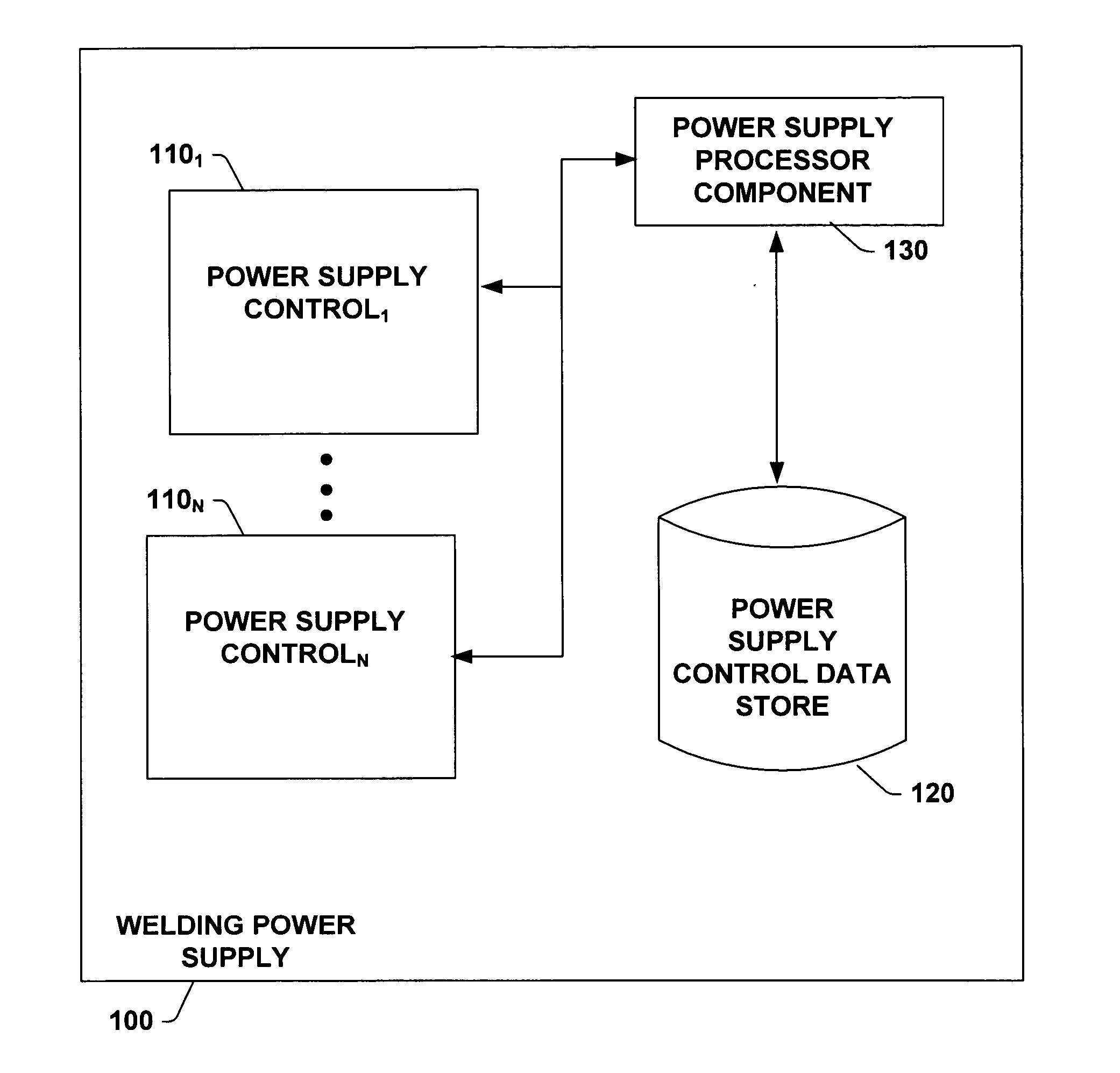
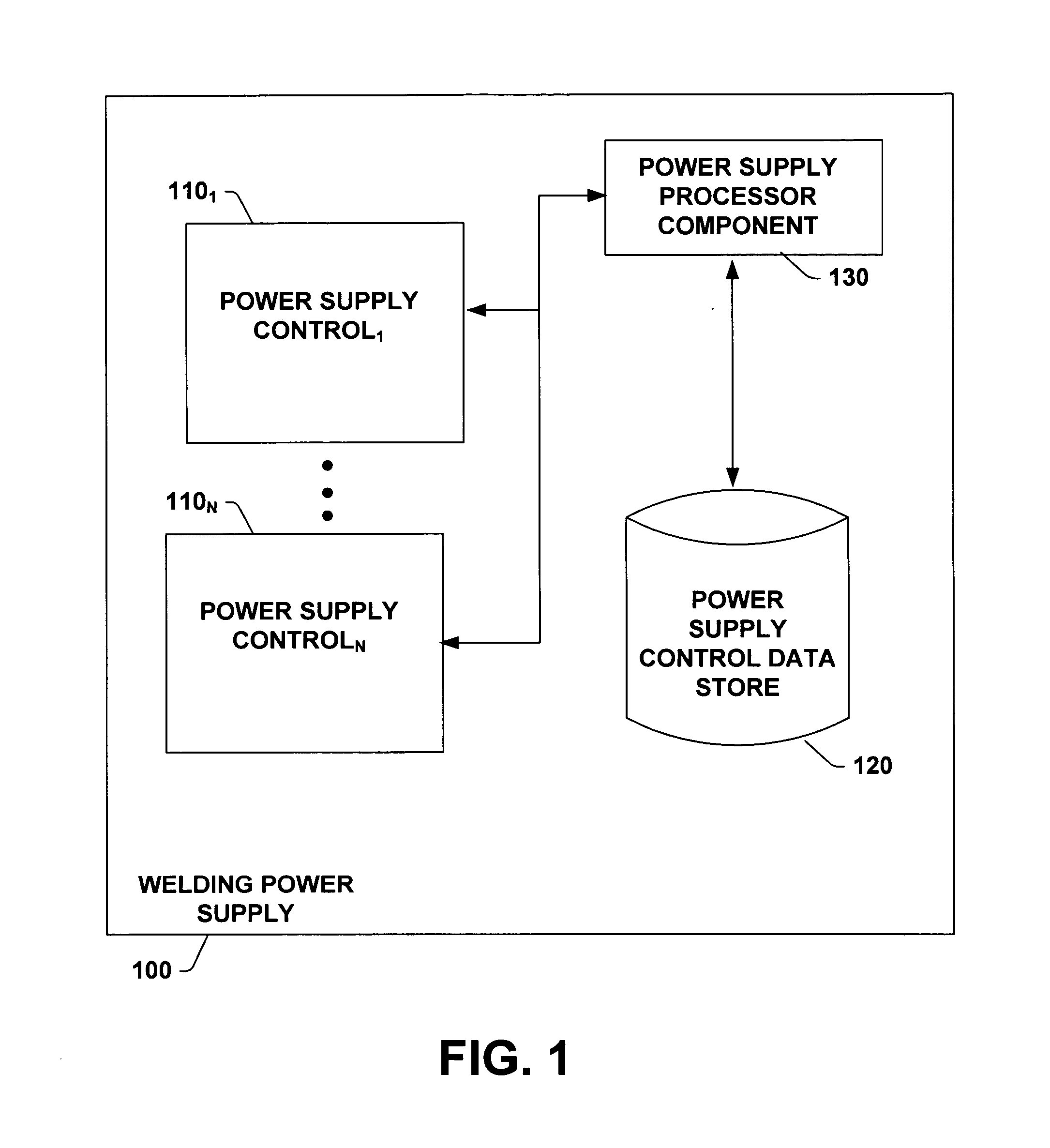
[0008] The present invention relates to an apparatus, system and method facilitating a welding power supply adapted to be reconfigured. In accordance with an aspect of the present invention, a welding power supply has at least one power supply control and a power supply configuration data store. The power supply control can command a power output of the welding power supply. The power supply configuration data store can store information, component change(s) and history associated with the power supply control. For example, the power supply configuration data store can store a date of configuration of the power supply control, a time of configuration of the power supply control, a hardware configuration of the welding power supply, a software version of the power supply control, a serial number and / or an identification of the power supply control, welding procedures installed in the welding power supply and / or a memory capacity of the welding power supply. The information stored in the power supply configuration data store can facilitate troubleshooting, servicing, operating, maintenance and / or upgrading of the welding power supply.
[0009] In accordance with another aspect of the present invention, a welding power supply can have an I / O component, a wire feed control component, a communications component and / or a welding procedure(s) data store. The I / O component can receive input signal(s) from node(s) of welding system(s). Based at least in part upon information from the I / O component, the power supply control can provide a power output to an output port. The wire feed control component can facilitate a rate of delivery of consumable wire utilized in the welding process. The communications component can facilitate communication between the welding power supply and remote system(s), for example, to facilitate troubleshooting, servicing, operating, maintenance and / or upgrading of the welding power supply. The communications component can be adapted for wireless communication utilizing a frequency adjusting wireless communication protocol (e.g., Bluetooth) with the remote system. Further, the welding power supply can be operatively coupled via a network to the remote system.

Problems solved by technology

Given the nature and requirements of modem, complex manufacturing operations, however, welding systems designers, architects and suppliers face increasing challenges in regard to upgrading, maintaining, controlling and servicing various welding locations.
Thus, controlling, maintaining and servicing multiple and isolated locations in large centers and / or across the globe has become more challenging, time consuming and expensive.
One such challenge relates to configuring welding power supplies to perform more than one welding task.
Another challenge facing welding power supplies relates to maintenance.
This may cause the process to stop or be disrupted during service outages relating to a poorly maintained welder, involving, for example, a welding power supply.

Method used


Image

  • Apparatus, system and method to facilitate reconfigurable welding power supply
  • Apparatus, system and method to facilitate reconfigurable welding power supply
  • Apparatus, system and method to facilitate reconfigurable welding power supply

Examples


Embodiment Construction

[0022] The present invention is now described with reference to the drawings, wherein like reference numerals are used to refer to like elements throughout. In the following description, for purposes of explanation, numerous specific details are set forth in order to provide a thorough understanding of the present invention. It may be evident to one skilled in the art that the present invention may be practiced without these specific details. In other instances, well-known structures and devices are shown in block diagram form in order to facilitate description of the present invention.

[0023] As used in this application, the term “component” is intended to refer to a electronic and / or computer-related entity, either hardware, a combination of hardware and software, software, or software in execution. For example, a component may be, but is not limited to being, a process running on a processor, a processor, an object, an executable, a thread of execution, a program, and a computer....


PUM

PropertyMeasurementUnit
poweraaaaaaaaaa
voltageaaaaaaaaaa
currentaaaaaaaaaa

Abstract

An apparatus, system and method for a welding power supply adapted to be reconfigured is provided. The welding power supply includes a power supply control and a power supply control data store. Optionally, the welding power supply can include a communications component, an I / O component, a wire feed control component and a welding procedure(s) store. The welding power supply can provide information regarding configuration of the welding power supply to other welding power supplies and remote system(s) to facilitate troubleshooting, servicing, operating, maintenance and / or upgrading of the welding power supply. The invention further comprises a methodology for providing configuration information to a welding power supply.

Description

CROSS REFERENCE TO RELATED APPLICATIONS [0001] This application is a continuation of U.S. Pat. No. 10 / 191,230 filed on Jul. 9, 2002, entitled APPARATUS, SYSTEM AND METHOD TO FACILITATE RECONFIGURABLE WELDING POWER SUPPLY, the entirety of which is incorporated herein by reference.TECHNICAL FIELD [0002] The present invention relates generally to computer and welding systems, and more particularly to an apparatus, system and method of facilitating a reconfigurable welding power supply. BACKGROUND OF THE INVENTION [0003] Welding power supplies are an integral part of electric arc welding systems. Welding systems may involve movement of a consumable electrode, for example, toward a work piece while current is passed through the electrode and across an arc developed between the electrode and the work piece. The electrode may be a non-consumable or consumable type, wherein portions of the electrode may be melted and deposited on the work piece. Power to the electrode is supplied by welding...

Claims


Application Information

Patent Timeline
Patent Type & Authority Applications(United States)
IPC IPC(8): B23K9/095B23K9/10B23K9/12H02M9/00
CPCB23K9/095B23K9/0953B23K9/124B23K9/1062B23K9/1006
Inventor SPEAR, THERESA CHIH-LEI MIAOBLANKENSHIP, GEORGE DARYL
Owner LINCOLN GLOBAL INC
Learn More