
Electrolytic cell stack with porous surface active electrode for removal of organic contaminants from water and method to purify contaminated water

a technology of active electrodes and electrolytic cells, applied in the field of stacks of electrolytic oxidation reduction cells, can solve problems such as oxidizing organic contaminants

Inactive Publication Date: 2005-02-17
EXTI
View PDF3 Cites 41 Cited by
  • Summary
  • Abstract
  • Description
  • Claims
  • Application Information

AI Technical Summary

Benefits of technology

Accordingly, it is an object of this invention to provide a system and method for remediating water by electrolytic oxidation / reduction of both organic and inorganic contaminants that overcomes the limitations of the background art, and permits remediation without the need for externally supplied reagents, catalysts, or oxidizing agents, and without the need for exotic or dangerous process conditions.
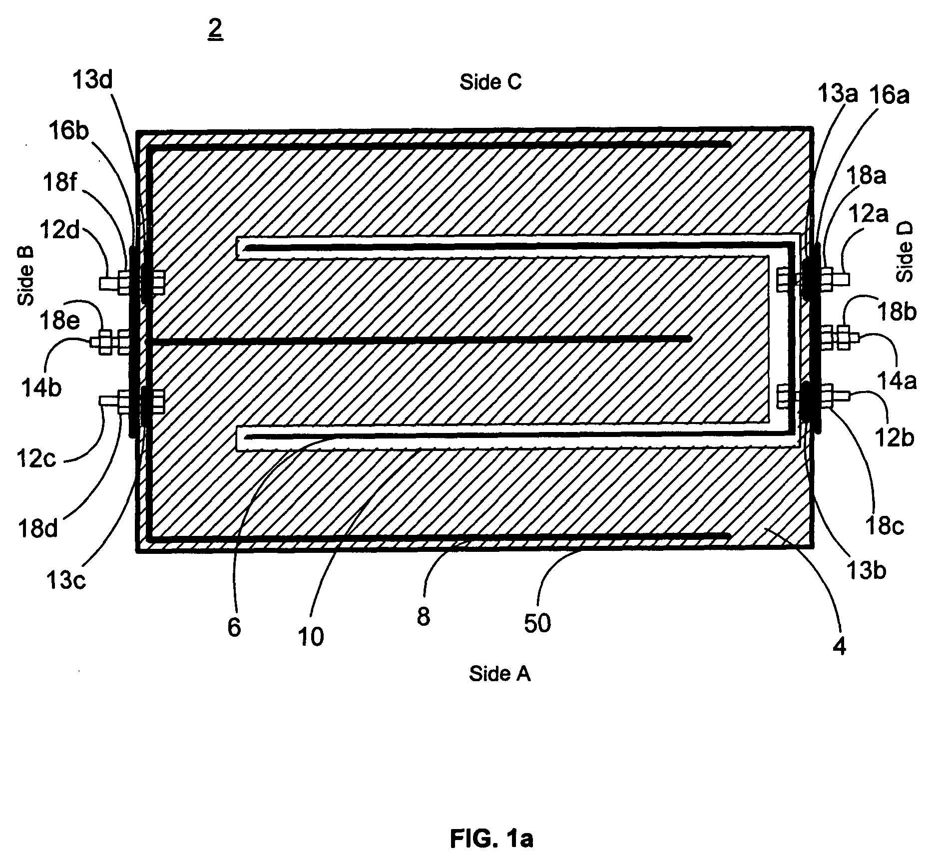
The electrolytic oxidation / reduction cell stacks of this invention may be connected in series or parallel, in any combination. A series connection will enhance the extent of remediation, whereas a parallel connection will enhance the volumetric capacity of the system. A series / parallel system will improve both the extent of remediation and the volumetric capacity.

Problems solved by technology

Where organic contaminants are to be removed, the porous electrode is positively charged with respect to the second electrode, thus oxidizing the organic contaminants.

Method used


Image

  • Electrolytic cell stack with porous surface active electrode for removal of organic contaminants from water and method to purify contaminated water
  • Electrolytic cell stack with porous surface active electrode for removal of organic contaminants from water and method to purify contaminated water
  • Electrolytic cell stack with porous surface active electrode for removal of organic contaminants from water and method to purify contaminated water

Examples


example 1

Remediation of Phenol Contaminated Industrial Wastewater Using Four Electrolytic Cell in One Vessel

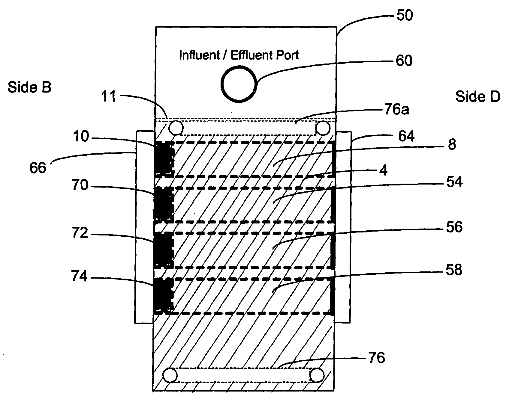
A sample of industrial wastewater containing 1400 ppm of phenol was initially filtered through 1.0 Micron filter and then introduced in to recirculation tank at a rate of 2.0 gpm. A flow of 20 gpm was taken from circulation tank containing 50 gals of water and introduced into a four electrolytic cell vessel as shown in FIG. 4. All four cells were connected in series arrangement. A 30 amp AC electrical current was applied at 30 volts (power consumption of 900 watts). A 2.0 gpm flow was discharged from the effluent of the electrolytic cell and the 18 gpm balance were returned to the recirculation tank. The experiment was conducted for 75 minutes and 150 gals of wastewater were treated.

TABLE IDETECTIONSAMPLELIMITRESULTSSAMPLE(ppm)(ppm)Phenol Prior to Treatment1.01400Phenol After Single-Pass1.040.0

The single pass at 2 gpm resulted in a 97% reduction in Phenol contamination.

example 2

Remediation of Phenol Contaminated Industrial Wastewater Using Four Electrolytic Cell in One Vessel

A sample of industrial wastewater containing 1400 ppm of phenol was initially filtered through 1.0 Micron filter and then introduced in to recirculation tank at a rate of 3.0 gpm. A flow of 20 gpm was taken from circulation tank containing 50 gals of water and introduced in to a four electrolytic cell vessel as shown in FIG. 4. All four cells were connected in series arrangement. A 30 amp AC electrical current was applied at 30 volts (power consumption of 900 watts). A 3.0 gpm flow was discharged from the effluent of the electrolytic cell and the 17 gpm balance were returned to the recirculation tank. The experiment was conducted for 75 minutes and 150 gals of wastewater were treated.

TABLE IIDETECTIONSAMPLELIMITRESULTSSAMPLE(ppm)(ppm)Phenol Prior to Treatment1.01400Phenol After Single-Pass1.050.0

The single pass at 3 gpm resulted in a 96.4% reduction in Phenol contamination in was...

example 3

Remediation of Phenol Contaminated Industrial Wastewater Using Four Electrolytic Cell in One Vessel

A sample of industrial wastewater containing 1400 ppm of phenol was initially filtered through 1.0 Micron filter and then introduced in to recirculation tank at a rate of 1.0 gpm. A flow of 20 gpm was taken from circulation tank containing 50 gals of water and introduced in to a four electrolytic cell vessel as shown in FIG. 4. All four cells were connected in series arrangement. A 30 amp AC electrical current was applied at 30 volts (power consumption of 900 watts). A 1.0 gpm flow was discharged from the effluent of the electrolytic cell and the 18 gpm balance were returned to the recirculation tank. The experiment was conducted for 75 minutes and 150 gals of wastewater were treated.

TABLE IIIDETECTIONSAMPLELIMITRESULTSSAMPLE(ppm)(ppm)Phenol Prior to Treatment1.01400Phenol After Single-Pass1.08.0

The single pass at 1 gpm resulted in a 99.4% reduction in Phenol contamination in was...


PUM

PropertyMeasurementUnit
voltagesaaaaaaaaaa
voltageaaaaaaaaaa
electric currentaaaaaaaaaa

Abstract

A wet oxidation / reduction electrolytic cell stack, system, and method for the remediation of contaminated water is disclosed. A porous electrode of large surface area produces powerful oxidizing agents in situ without having to add any reagents, oxidizers, or catalysts to the water to be treated. Further, by the appropriate selection of electrode material, organic contaminants may be absorbed onto the surface of the electrode and subsequently oxidized to provide a dynamically renewable porous electrode surface. Flow rates, and power requirements may be tailored to the specific moieties to be removed, thus allowing local treatment of specific waste streams resulting in direct discharge to a publicly owned treatment works (POTW) or surface water discharge. A novel feature of this invention is the ability to remove both organic and metal contaminants without the addition of treatment reagents or catalysts.

Description

FIELD This invention is directed to an apparatus and method for the remediation of contaminated water, and more particularly to a stack of electrolytic oxidation-reduction cells for the continuous remediation of water, in particular the treatment of organic and inorganic contaminants in contaminated groundwater, surface water, and wastewater, and continuous processes therefore. BACKGROUND Environmental laws and their resulting regulations are placing an increased emphasis on the water quality of both surface waters and ground water. Previously acceptable methods for disposing of contaminated water are now either no longer allowed or subject to strict permit requirements. Discharges of industrial wastewater, for example, must meet stringent discharge concentration limits for heavy metals such as copper, lead, nickel, mercury, cadmium, chromium VI, zinc, and silver. Other controlled pollutants include chlorofluorocarbons, pesticides, and halides. Municipalities now generally require...

Claims


Application Information

Patent Timeline
Patent Type & Authority Applications(United States)
IPC IPC(8): C02F1/461C02F1/467
CPCC02F1/46109C02F1/4672C02F2305/023C02F2101/32C02F2101/327C02F2001/46161
Inventor KAZI, ABDULLAHHAYS, ROY L.
Owner EXTI
Learn More