
Method and apparatus of cryogenic cooling for high temperature superconductor devices

Inactive Publication Date: 2005-02-10
SUPERPOWER INC
View PDF15 Cites 5 Cited by
  • Summary
  • Abstract
  • Description
  • Claims
  • Application Information

AI Technical Summary

Benefits of technology

[0004] Briefly, in accordance with the present invention, a method is provided for designing a liquid-cryogen-based cryogenic cooling system for HTS devices that have the characteristics of lower operating temperature of liquid cryogen to improve the critical current density of HTS materials while at the same time substantially increasing the dielectric strength of the liquid cryogen, making such a cryogenic cooling system suitable for high-voltage applications. Such a method comprises the steps of maintaining a pressurized cryogen within the cryogen containment vessel that contains both liquid and gaseous regions of the cryogen. It further includes steps of maintaing the temperature of a portion or all of the liquid cryogen at and below its boiling temperature and within its sub-cooled temperature range using cryocooling means.

Problems solved by technology

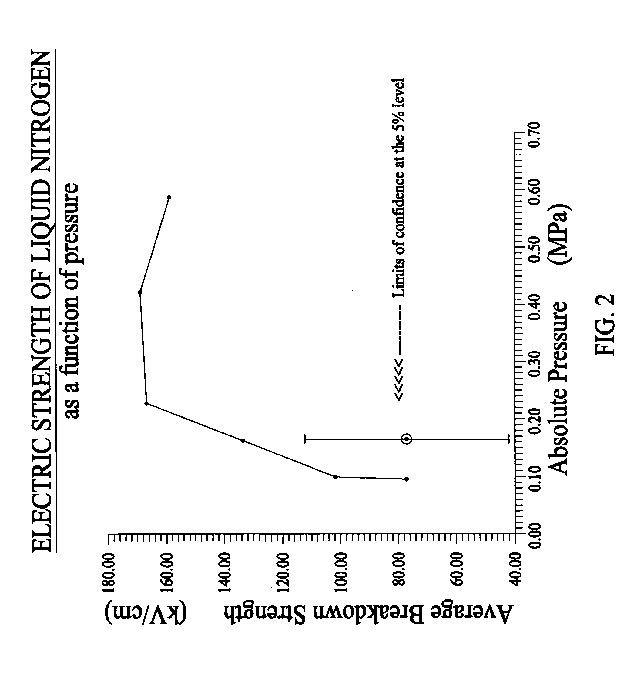
Even though the prior art increases the performance of HTS materials by lowering the boiling temperature of liquid nitrogen through lowering its pressure, it is in the expense of significantly degrading the dielectric strength of liquid nitrogen and as a consequence such cooling systems are not suitable for high-voltage HTS applications.
Bubbles, especially large size bubbles, tend to reduce the dielectric strength of liquid nitrogen.
Therefore method of lowering liquid nitrogen temperature by lowering its pressure will have negative impact on both factors that govern the dielectric strength of liquid nitrogen.
Cooling systems based on such and similar approached are therefore ill suited for high-voltage HTS applications.

Method used


Image

  • Method and apparatus of cryogenic cooling for high temperature superconductor devices
  • Method and apparatus of cryogenic cooling for high temperature superconductor devices
  • Method and apparatus of cryogenic cooling for high temperature superconductor devices

Examples


Embodiment Construction

[0013] The present invention generally relates to a cryogenic cooling systems for HTS device that have high-voltage applications even though it can also be applied to HTS devices that have other general purposes. The method of providing such a cryogenic cooling system includes maintaining a pressurized cryogen region that comprises a liquid as well as gaseous region, to above one absolute atmospheric pressure. The method further involves maintaining temperature of part or all of the liquid cryogen regions to below its boiling temperature (sub-cooled) using cooling means such as a cryogenic refrigerator (cryocooler).

[0014] Briefly, in accordance with the present invention, a method is provided for designing a liquid-cryogen-based cryogenic cooling system for HTS devices that have the characteristics of lower operating temperature of liquid cryogen to improve the critical current density of HTS materials while at the same time substantially increasing the dielectric strength of the l...


PUM


Abstract

A method and apparatus for providing cryogenic cooling to HTS devices, in particular those that are used in high-voltage electric power applications. The method involves pressurizing liquid cryogen to above one atmospheric pressure to improve its dielectric strength, while sub-cooling the liquid cryogen to below its saturation temperature in order to improve the performance of the HTS components of the device. An apparatus utilizing such a cooling method consists of a vessel that contains a pressurized gaseous cryogen region and a sub-cooled liquid cryogen bath, a liquid cryogen heating coupled with a gaseous cryogen venting scheme to maintain the pressure of the cryogen to a value in a range that corresponds to optimum dielectric strength of the liquid cryogen, and a cooling system that maintains the liquid cryogen at a temperature below its boiling point to improve the performance of HTS materials used in the device.

Description

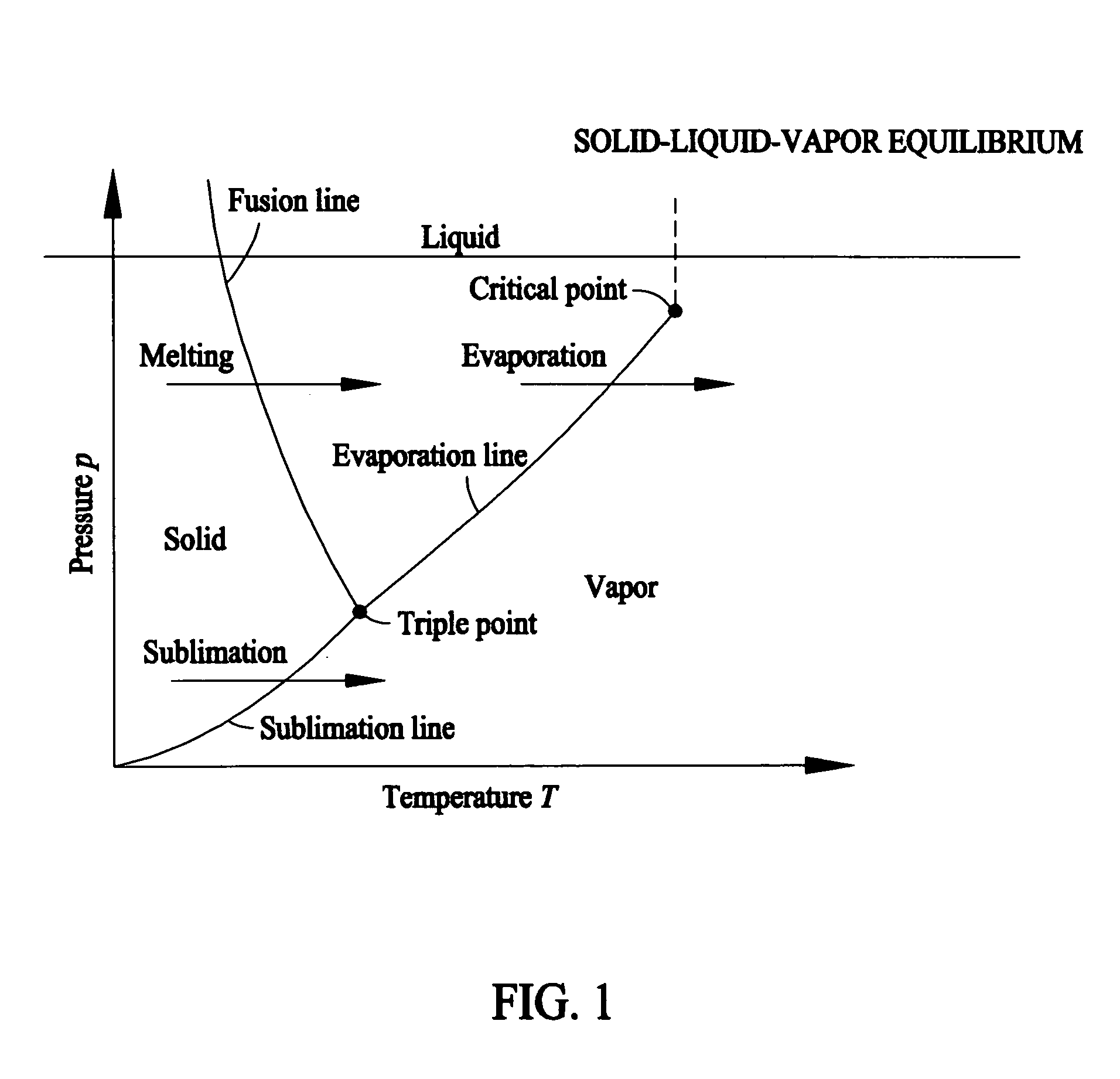
BACKGROUND [0001] The invention relates generally to a cryogenic cooling system for high temperature superconductor (HTS) devices and more particularly to a cryogenic cooling system for HTS devices having high-voltage electric power applications. [0002] There exists HTS cooling systems that use the properties of liquid nitrogen to achieve cryogenic cooling. Normally, liquid nitrogen is used at one atmospheric pressure (0.1 MPa) where its operating temperature (boiling point) is at 77 degrees Kelvin. However, since the critical current density of HTS materials improves significantly at temperatures lower than 77 K, methods have been developed to reduce the temperature of the liquid nitrogen by manipulating its operating environment. FIG. 1 is a p(pressure)-T(temperature) diagram showing the relationship amongst the p, T and the three phases (solid, liquid and vapor / gas) of a typical substance. For nitrogen, the “Triple Point” is about 63.15 K at 12.53 KPa. This shows by reducing the ...

Claims


Application Information

Patent Timeline
IPC IPC(8): F17C1/00F17C7/04F25B19/00F25DF25D19/00F25D23/12H01F6/04
CPCF17C1/00H01F6/04F17C2201/032F17C2201/056F17C2203/0308F17C2203/0391F17C2203/0604F17C2203/0617F17C2205/0111F17C2205/0126F17C2205/018F17C2205/0338F17C2221/014F17C2223/0161F17C2223/033F17C2227/0304F17C2227/0353F17C2227/0355F17C2227/0379F17C2250/061F17C2250/0626F17C2250/0631F17C2260/02F17C2260/026F17C2260/033F17C2270/0527F25D19/006F17C2201/0109F25B9/00F25B49/00
Inventor YUAN, XINGMINE, SUSUMU
Owner SUPERPOWER INC
Learn More