
Method of bone expansion and compression for receiving a dental implant using threaded expanders

Inactive Publication Date: 2005-02-03
EVOLLUTION IP HLDG
View PDF6 Cites 15 Cited by
  • Summary
  • Abstract
  • Description
  • Claims
  • Application Information

AI Technical Summary

Benefits of technology

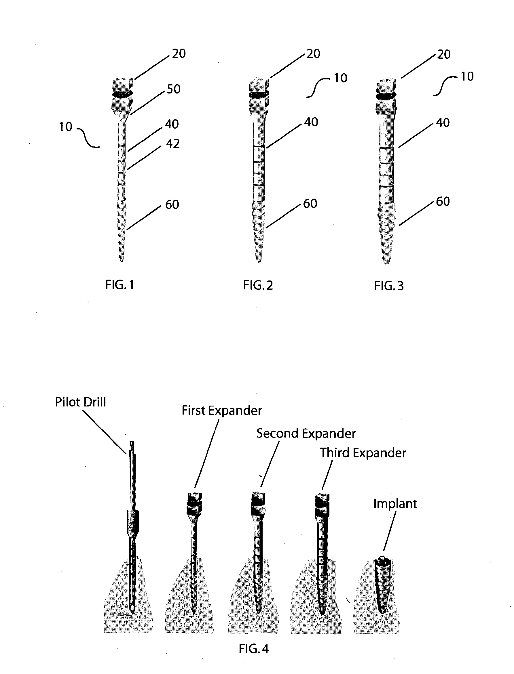
[0011] In a further aspect, the present invention relates to a method of expansion of bone tissue for receiving a dental implant. The method comprises the steps of creating a small initial osseotomy site in the maxilla or the mandable to a desired depth using a pilot drill at a predetermined implant location; screwing a first threaded expander into the osseotomy site, thereby expanding the osseotomy site laterally; allowing the first expander staying in the osseotomy site for a sufficient amount of time to impress an interior wall of the osseotomy site; retrieving the first expander by screwing the first expander out in a reverse direction; and repeating the expansion steps using a second threaded expander which has an increasing outer diameter and a substantially same thread structure to the dental implant, to further expand the osseotomy site laterally to a final diameter which is complementary, but narrower than an outer diameter of the dental implant so that expanded osseotomy site enables the implant to sufficiently bite into and uniformly engage with surrounding bone tissue. Each expander and the implant are carefully started following the thread of the previous expander.
[0013] It is an object of the present invention to provide improved threaded bone expansion devices which provides a gentle expansion of bone tissue at the implant site; wherein the devices can be handled conveniently by existing dental tools used for placing implants.
[0014] It is another object of the present invention to provide a method of sequential expansion of bone tissue using a set of threaded bone expansion devices to provide an implant site which has a complementary structure and dimensions to the implant to be placed, so that the implant receives an optimal support from and optimal engagement with surrounding bone tissue.

Problems solved by technology

However, implant placement is often compromised by the quality of bone and available ridge width.
However, valuable bone tissue is removed during drilling, consequently fitting strength of an implant is not guaranteed, particularly when the surrounding bone issue is soft and porous.
The drilling for the formation of osseotomy sites in the upper jaw for implant placement proves to be unfavorable, since bone tissue is removed from the soft bone.
However, the osteotome technique is also a traumatic technique, consequently, it is accompanied by various disadvantages.
Among the most important disadvantages, one is the damage to the bone, up to and including breaking and chipping of the bone, as a result of tension created at the dental base with each tap of the small hammer onto the osteotome.
In some instances, a complete deterioration of the dental base can occur, and this deterioration of the dental base requires extensive repairs.
Another disadvantage is the formation of simple, slightly conical cavities in the jaw, which does not provide a reliable bed for the fixation especially of screw-type implants.
Since implants have different outer contours, particularly graduated cylinder implants with screw threads, the smooth, slightly conical osseotomy site formed in the jaw by osteotome is not structurally complementary to the threaded implants.
This can results in difficulty in the osteointegration and difficulty in the cohesion based on an incomplete contact between the implant and bone.
A further disadvantage is the alignment defect of the fixation axis because the bone expansion can not be controlled or adjusted.
An additional disadvantage is the appearance of a hammer, the shock of the hammer on the metal and resulting fear of the patients.
However, the screw threads do not correlate to the implant structure, and the prepared bed does not ensure proper implant contact into surrounding bone issues.

Method used


Image

  • Method of bone expansion and compression for receiving a dental implant using threaded expanders
  • Method of bone expansion and compression for receiving a dental implant using threaded expanders

Examples


Embodiment Construction

[0020] In one aspect, the present invention provides a set of threaded bone expanders of the same threaded structure, with increasing diameters, for expanding bone, particularly of the narrow ridge, for receiving a dental implant. The threaded expander set can be used in combination with existing ridge expanding / splitting techniques allowing gentle expansion of the osseotomy site. The osseotomy site is an opening in the maxilla or the mandable for placement of a dental implant.

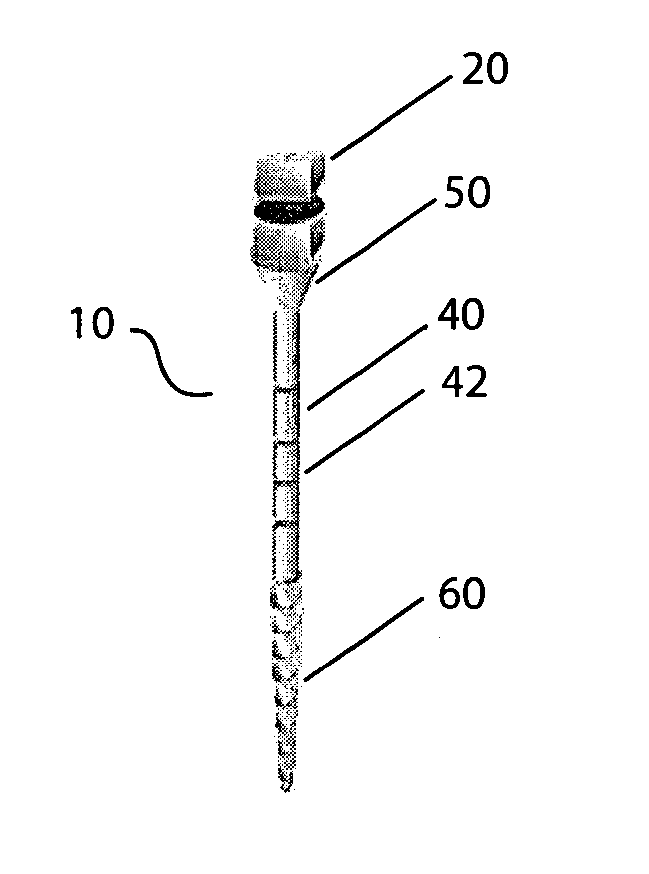
[0021] In one embodiment, as shown in FIG. 1, the threaded expander 10 has an one-piece structure, which comprises a top 20 for engaging with a dental ratchet, a cylindrical shaft 40, a transition 50 between cylindrical shaft 40 and top 20, and a threaded expansion tip 60 connected to cylindrical shaft 40. The expander 10 can be made of stainless steel or other suitable materials used in dentistry.

[0022] The top 20 of the expander 10 is the similar to the hex top in terms of function for engaging with a ratc...


PUM


Abstract

A method and devices for bone tissue expansion and compression for receiving a dental implant are disclosed. The method includes the steps of creating an initial osseotomy site in the maxilla or the mandable using a pilot drill; screwing a first threaded expander into the site to expand the site laterally; and allowing the expander staying in the site for a short time to impress the interior wall of the osseotomy site; then retrieving the first expander. These steps are repeated using a second, and / or third threaded expander having an increasing outer diameter to further expand the osseotomy site to a final diameter which is complementary, but narrower than the diameter of the dental implant so that expanded osseotomy site enables uniform engagement of the implant with the bone tissue. A preparation drilling to extend osseotomy site only at cortical level can be incorporated for hard bone and larger implants.

Description

FIELD OF INVENTION [0001] The present invention relates to a method and devices for expanding and compressing bone for receiving a dental implant. More specifically, the present invention relates to a method of using a series of threaded expanders to gently expand an osseotomy site as an alternative to removal of bone by drilling and tapping by osteotome. BACKGROUND OF THE INVENTION [0002] Dental implants are used to secure a prosthetic received and other dental items in the oral cavity. One of the important goals of implant therapy is to achieve a firm, durable, intra-oral connection to the maxilla and mandable with a screw-type or cylinder-type structure made of a biologically compatible material. However, implant placement is often compromised by the quality of bone and available ridge width. [0003] The creation of an osseotomy site for placement of implants by means of drilling is well known in dentistry. However, valuable bone tissue is removed during drilling, consequently fit...

Claims


Application Information

Patent Timeline
IPC IPC(8): A61C8/00
CPCA61C8/0089A61C8/00A61C3/02
Inventor NILO, PATRICIOHOLLANDER, BRUCE L.
Owner EVOLLUTION IP HLDG
Learn More