
Liquid crystal display device

a display device and liquid crystal technology, applied in mechanical devices, lighting and heating devices, instruments, etc., can solve the problems of deteriorating an entertainment effect brought about by displayed images, difficult to impart the player a feeling of integrity with the display, etc., and achieve the effect of deteriorating an entertainment effect and low brightness

Active Publication Date: 2005-02-03
PANASONIC LIQUID CRYSTAL DISPLAY CO LTD
View PDF2 Cites 12 Cited by
  • Summary
  • Abstract
  • Description
  • Claims
  • Application Information

AI Technical Summary

Benefits of technology

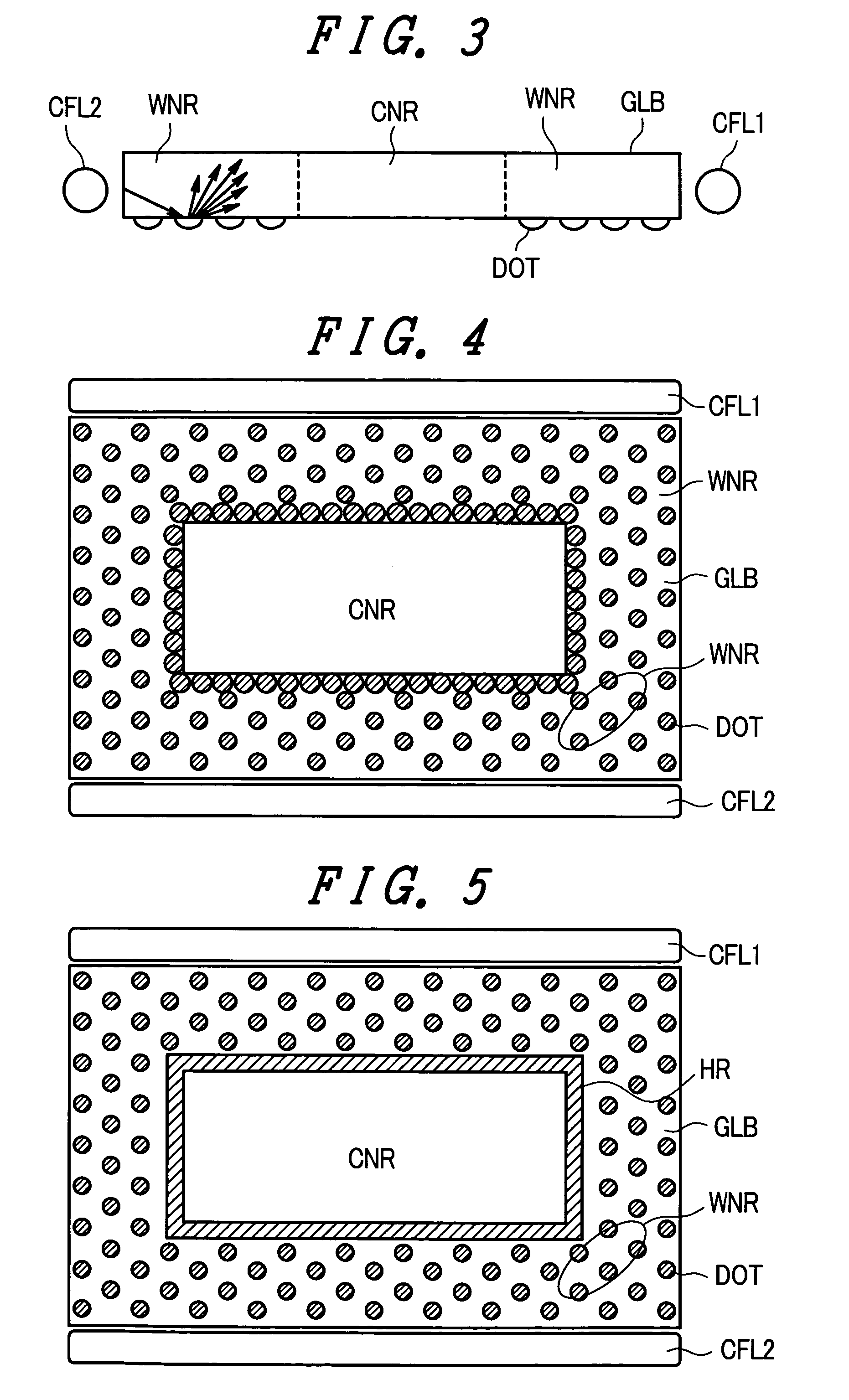
[0007] However, since the light reflection treatment such as the dot printed film (including a discontinuous printed film, a circular shape, a polygonal shape, a stripe shape and the like) is not provided to the region of the light guide plate which faces the transmission region of the liquid crystal display panel, a reflection quantity of light from the light source is small around the transmission region, that is, in the vicinity of a boundary between the display region and the transmission region whereby this region exhibits the low brightness compared to the display region. That is, the periphery of the transmission region becomes dark. Further, due to the relationship with the arrangement of the light source, the brightness irregularities arise in the periphery of the transmission region. As a result, the boundary between the display region and the transmission region becomes obscure thus deteriorating an entertainment effect brought about by displayed images.

Problems solved by technology

However, with respect to the slot-machine-type game machine having such a constitution, since the liquid crystal display panel is arranged relatively remote from the rotary display drum unit, when a player performs a game while focusing his or her attention on the rotary display drums, the player is hardly conscious of displays on the liquid crystal display panel whereby the game machine has a drawback that it is difficult to impart the player a feeling of integrity with the displays.
As a result, the boundary between the display region and the transmission region becomes obscure thus deteriorating an entertainment effect brought about by displayed images.

Method used


Image

  • Liquid crystal display device
  • Liquid crystal display device
  • Liquid crystal display device

Examples


embodiment 1

[0036] [Embodiment 1]

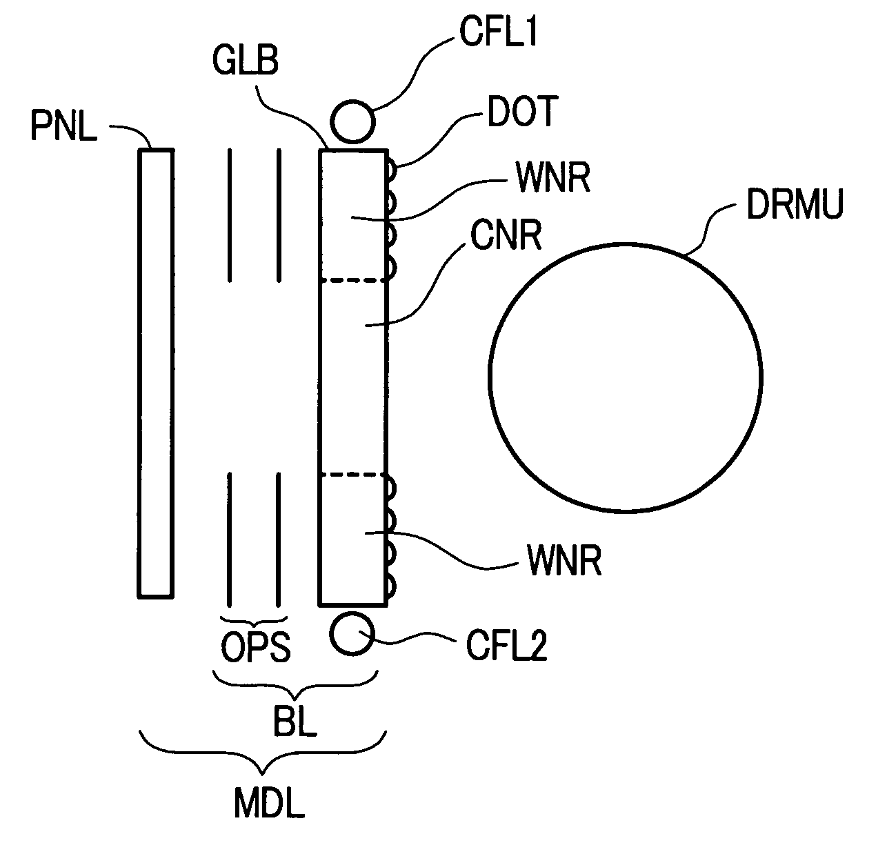
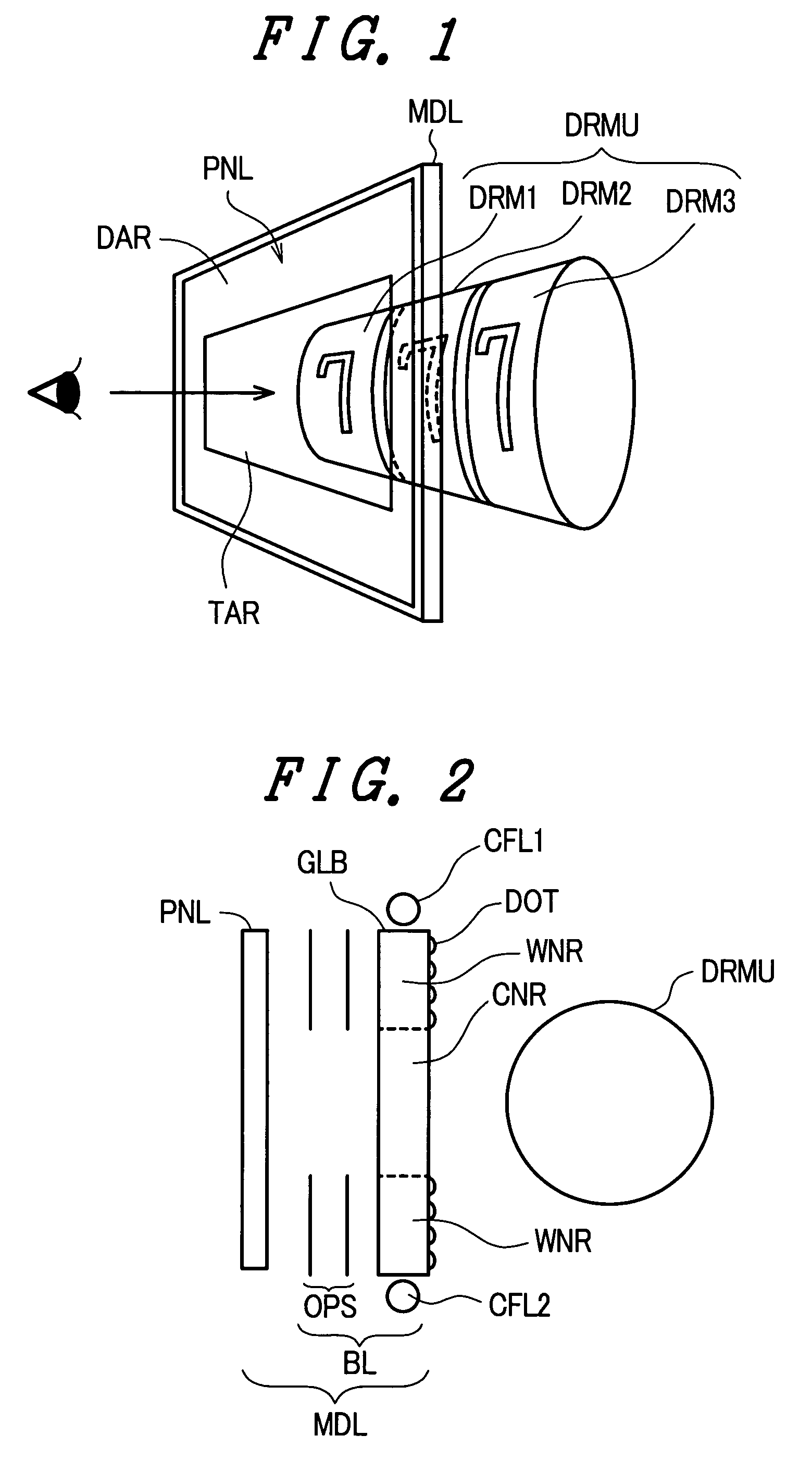
[0037]FIG. 4 is a back view of a light guide plate which constitutes a backlight of embodiment 1 of a liquid crystal display device according to the present invention, wherein FIG. 4 shows light sources CFL1, CFL2 together with the light guide plate GLB. In this embodiment, a transmission portion corresponding region CNR is formed in the vicinity of a center portion of the light guide plate GLB. The light reflection treatment is applied to the window-frame portion corresponding region WNR excluding the transmission portion corresponding region CNR thus forming a light reflection treatment portion. In this embodiment, a dot printed film DOT is printed on the window-frame portion corresponding region WNR around the transmission portion corresponding region CNR. Further, the printing is performed such that the density of the dot printed film in the vicinity of the inner periphery of the transmission portion corresponding region CNR is set higher than the density of...

embodiment 2

[0039] [Embodiment 2]

[0040]FIG. 5 is a back view similar to FIG. 4 showing the light guide plate which constitutes a backlight of the embodiment 2 of a liquid crystal display device according to the present invention. In this embodiment, the light reflection treatment is applied to the window-frame portion corresponding region WNR except for the transmission portion corresponding region CNR provided in the vicinity of the center portion of the light guide plate GLB. The dot printed film DOT is printed on the window-frame portion corresponding region WNR around the transmission portion corresponding region CNR. Further, to the vicinity of the inner periphery of the transmission portion corresponding region CNR, mat printed films HR made of a printing material as the material of the dot printed film DOT is printed.

[0041] In this manner, by providing the mat printed film HR in the vicinity of the inner periphery of the transmission portion corresponding region CNR, the light reflectio...

embodiment 3

[0042] [Embodiment 3]

[0043]FIG. 6A an FIG. 6B are explanatory views of a light guide plate which constitutes a backlight of the embodiment 3 of the liquid crystal display device according to the present invention, wherein FIG. 6A is a back view and FIG. 6B is a cross-sectional view taken along a line Y-Y′ in FIG. 6A. The backlight of this embodiment uses the light guide plate GLB having a wedge-shaped cross section and a light source CFL is arranged only along one side edge where the light guide plate GLB has the large thickness. Then, the light reflection treatment is applied to the window-frame portion corresponding region WNR excluding the transmission portion corresponding region CNR which is provided in the vicinity of the center portion of the light guide plate GLB. A dot printed film DOT is printed on the window-frame portion corresponding region WNR around the transmission portion corresponding region CNR and mat printed films HR made of a printing material similar to the ma...


PUM

PropertyMeasurementUnit
light reflectanceaaaaaaaaaa
thicknessaaaaaaaaaa
transmissionaaaaaaaaaa

Abstract

A display device suitable for a game machine has dot printed films which are printed on a light guide plate which constitutes a backlight for illuminating a liquid crystal display panel. The dots of the dot printed films are arranged more densely in a window-frame portion corresponding region, which faces a display region of the liquid crystal display panel, and in the vicinity of an inner periphery of a transmission portion corresponding to a region which faces a transmission region.

Description

BACKGROUND OF THE INVENTION [0001] The present invention relates to a liquid crystal display device, and more particularly to a liquid crystal display device which is suitably used in a slot-machine-type game machine. [0002] The slot-machine-type game machine is configured such that the game machine includes a rotary display drum unit which consists of three rotary display drums, for example, which have rotary shafts thereof horizontally aligned with each other at the center of a surface which faces a player, wherein when a player pushes a start button, these rotary display drums are rotated and, thereafter, when the player pushes stop buttons corresponding to the respective rotary display drums, the rotary display drums are sequentially stopped. [0003] Then, when numerals, symbols and patterns described on side surfaces of the respective rotary display drums are stopped in a state that they agree with each other, the player becomes a winner of the game and acquires a large number o...

Claims


Application Information

Patent Timeline
Patent Type & Authority Applications(United States)
IPC IPC(8): F21V8/00G02B6/00G02F1/13357
CPCG02B6/0043G07F17/3211G02F1/133615G02B6/0046
Inventor SHIRAISHI, YASUHISAHIRAYAMA, HISAOTEZUKA, AKIOHASEGAWA, MAKOTO
Owner PANASONIC LIQUID CRYSTAL DISPLAY CO LTD
Learn More