
Hydraulic control system for vehicle

Inactive Publication Date: 2005-02-03
ADVICS CO LTD
View PDF3 Cites 7 Cited by
  • Summary
  • Abstract
  • Description
  • Claims
  • Application Information

AI Technical Summary

Benefits of technology

[0008] It is an object of the present invention to provide a hydraulic control system, with a simple configuration, that can prevent water entry to a solenoid valve housing chamber, and, even in the case that water entry occurs, can allow the water to be quickly drained.
[0010] Therefore, the labyrinth portion is capable of inhibiting as well as allowing water entry through the air vent. The labyrinth portion with this configurations may be formed as a part of the lower space, and thus may be formed integrally and simultaneously with a casing of the solenoid valve housing portion. Therefore, it is possible to easily manufacture the hydraulic control system without requiring design changes to be made, for example, the structure of the hydraulic unit or the installation position of the solenoid valve.
[0011] According to a second aspect of the present invention, even when fluid, namely water, enters the lower space through an upper communication hole or a lower communication hole of the first partition plate, the water flows down from the upper communication hole to the lower communication hole along the first partition plate which is inclined. Thus, the water is easily drained through the lower communication hole toward the air vent which is positioned below. Accordingly, the first partition plate and the lower communication hole are capable of functioning as a drain passage for the lower space, and water is prevented from remaining on the first partition plate.
[0013] According to a third aspect of the present invention, a second partition plate is disposed above the air vent provided at the lowermost portion of the solenoid valve housing chamber. The first partition plate is disposed above the second partition plate, and further, the lower space is formed above the first partition plate. Therefore, the fluid, which is the water in this case, which flows upward through the air vent first strikes the second partition plate, whereby direct water entry into the lower space is inhibited. Further, on some occasions, water may enter the lower space through the communication hole of the second partition plate enters the lower space through the upper communication hole or the lower communication hole of the first partition plate. Even in this case, the water flows from the upper communication hole to the lower communication hole along the first partition plate which is inclined, and is easily drained through the lower communication hole to the second partition plate disposed below. Then, the water can be drained to the outside of the solenoid valve housing chamber through the communication hole to the air vent disposed below. Accordingly, water is less likely to enter the solenoid valve housing chamber, and water that enters the solenoid valve housing chamber can be easily drained.
[0014] Further, according to a fourth aspect of the present invention, even when fluid entry occurs through the air vent, the fluid can be guided to a communication hole for inflow that has a larger opening area than a communication hole for discharge. Moreover, while the thus guided fluid enters the upper communication hole which is disposed at a comparatively high position, the momentum of the fluid can be attenuated. Therefore, it is possible to easily inhibit the fluid from entering the lower space.
[0015] Note that, in the solenoid valve housing chamber, a pump-motor electric supply terminal is disposed above the lower communication hole of the first partition plate in the up-down direction. Accordingly, fluid is easily drained through the lower communication hole, and the pump-motor electric supply terminal (through which a relatively large current passes) is less likely to be immersed in fluid.

Problems solved by technology

However, when an in-vehicle air-tight chamber is subjected to a severe temperature change, water vapor is likely to enter the air-tight chamber and dew is likely to condense therein.
However, manufacturing of the air passage requires an additional processing for the housing and a structural change in a motor portion, whereby cost is increased.

Method used


Image

  • Hydraulic control system for vehicle
  • Hydraulic control system for vehicle
  • Hydraulic control system for vehicle

Examples


Embodiment Construction

[0021] The present invention will be described further with reference to various embodiments in the drawings.

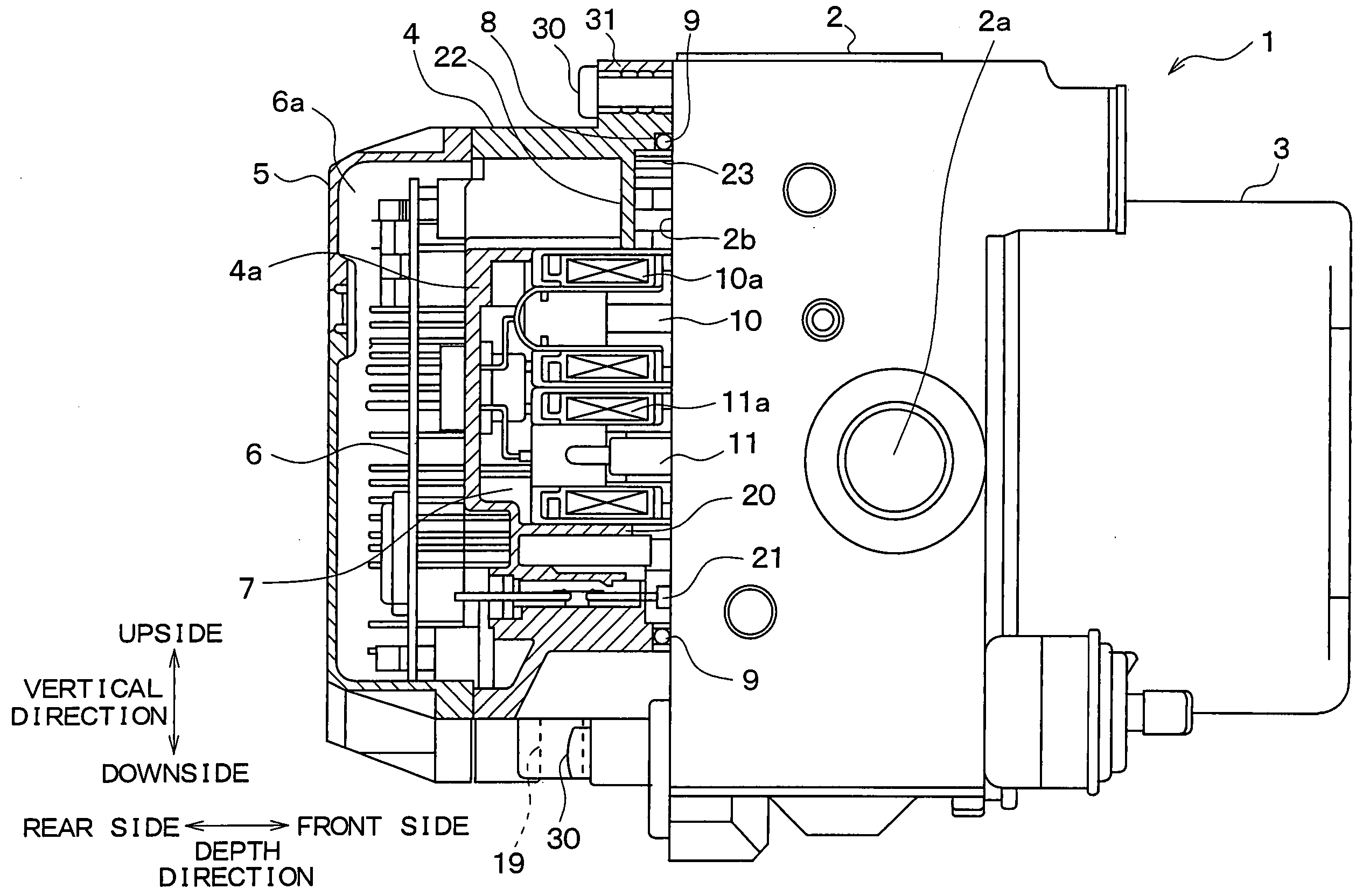
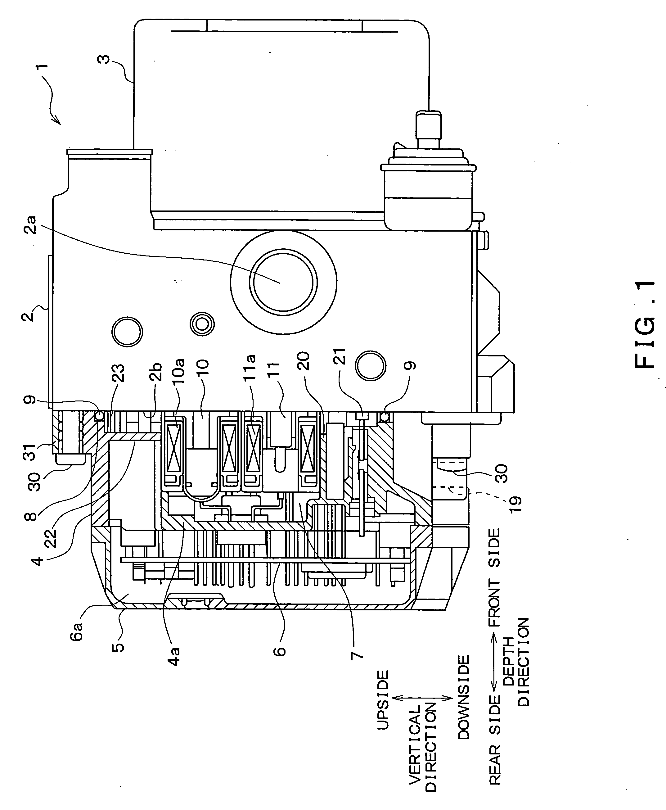
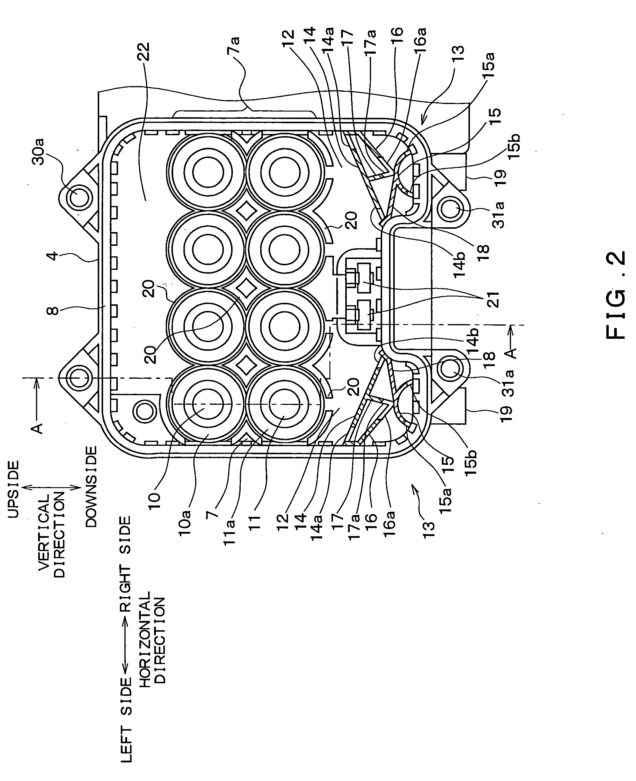
[0022] A hydraulic control system for a vehicle according to an embodiment of the present invention will be explained in detail referring to the drawings. FIG. 1 is a front view of a hydraulic control system 1 (including a partial sectional view cut along line A-A in FIG. 2); FIG. 2 is a side view of a solenoid cover 4 viewed from a left side of FIG. 1; FIG. 3 is an enlarged view of a left labyrinth portion 13 in FIG. 2; and FIG. 4 is a sectional view of the labyrinth portion 13 taken along line B-B as shown in FIG. 3. Respective top sides of the drawings in FIGS. 1 to 4 indicates an upside in the vertical direction when the hydraulic control system 1 is mounted in a vehicle body (hereinafter also simply referred to as “above” or “upside”). Furthermore, in FIGS. 1 and 4, a left side and a right side of the drawing are defined as a rear side and a front side in the depth dire...


PUM


Abstract

A solenoid cover includes a solenoid valve housing chamber housing solenoids of solenoid valves that project outwards from a hydraulic unit and a lower space therebelow. Two labyrinth portions with a fluid passage formed by a plurality of partition plates and communication holes are provided so as to be symmetrical with each other in a left-right direction below the lower space. An air vent communicates with the outside and which serves as a water drain is provided below each labyrinth portion. When a pressure in the solenoid valve housing chamber becomes negative due to a temperature decrease, water flows through the air vent at a high flow rate. Then, the water entering through the upper communication hole flows down along the partition plate toward the lower communication hole, which easily enables the water to be drained to the outside.

Description

CROSS REFERENCE TO RELATED APPLICATION [0001] This application is based upon and claims the benefit of Japanese Patent Application No. 2003-282883 filed on Jul. 30, 2003, the content of which are incorporated herein by reference. FIELD OF THE INVENTION [0002] The present invention relates to a hydraulic control system for a vehicle. BACKGROUND OF THE INVENTION [0003] Conventionally, a vehicle has a hydraulic control system which includes a hydraulic unit for regulating a wheel cylinder pressure by actuating a solenoid valve, a pump motor which serves as an actuator for regulating a hydraulic pressure, an electronic control system which controls the hydraulic unit and drives the pump motor, and the like. In order to reduce the size of the hydraulic control system, the hydraulic unit, the pump motor and the electronic control system are integrated into a module. [0004] In a hydraulic control system like this, it is particularly important that a solenoid portion of the solenoid valve i...

Claims


Application Information

Patent Timeline
IPC IPC(8): B60T8/34B60T8/36
CPCB60T8/368
Inventor SANADA, SATOSHI
Owner ADVICS CO LTD
Learn More