
Methods and apparatus for heat treatment and sand removal for castings

a technology of heat treatment and castings, applied in the field of metalurgical casting processes, can solve the problems of deformation of the core and the tendency of the binding agent to dissolv

Inactive Publication Date: 2005-02-03
CONSOL ENG
View PDF60 Cites 26 Cited by
  • Summary
  • Abstract
  • Description
  • Claims
  • Application Information

AI Technical Summary

Benefits of technology

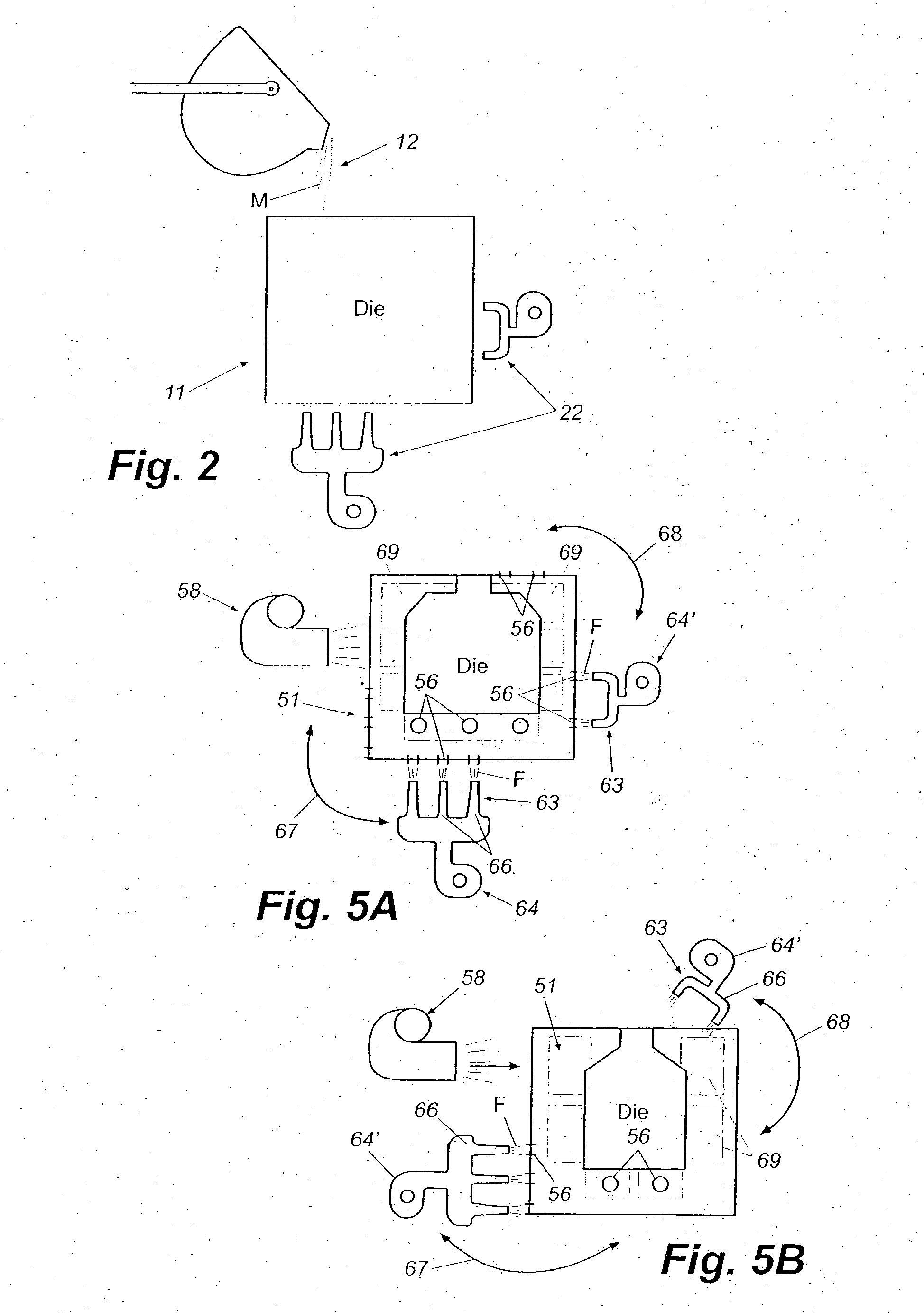
[0007] In one embodiment of the present invention for sand core removal and heat treatment of castings, a molten material, such as aluminum or other metal, is poured into molds or dies. The temperature of the molds or dies can be adjusted, either by beating or cooling, prior to the pouring of the molten material therein in order to make the casting process more efficient. The molds or dies may be preheated to maintain the temperature of the metal close to a heat treatment temperature as the castings are formed in the molds. The castings are then removed from their molds and are each placed in a pre-defined position on a saddle that has known x, y and z coordinates. Each saddle generally is configured to receive one or more castings in a fixed orientation or position with the x, y, and z coordinates of each casting located in a known, indexed position or orientation so that the core apertures of the castings formed by the sand cores are oriented or aligned in known, indexed positions. The saddles further can include locating devices to guide and help maintain the castings in their desired, known indexed position.

Problems solved by technology

When the cores are exposed to the fluid, the binder tends to dissolve and the core degrades.

Method used


Image

  • Methods and apparatus for heat treatment and sand removal for castings
  • Methods and apparatus for heat treatment and sand removal for castings
  • Methods and apparatus for heat treatment and sand removal for castings

Examples


first embodiment

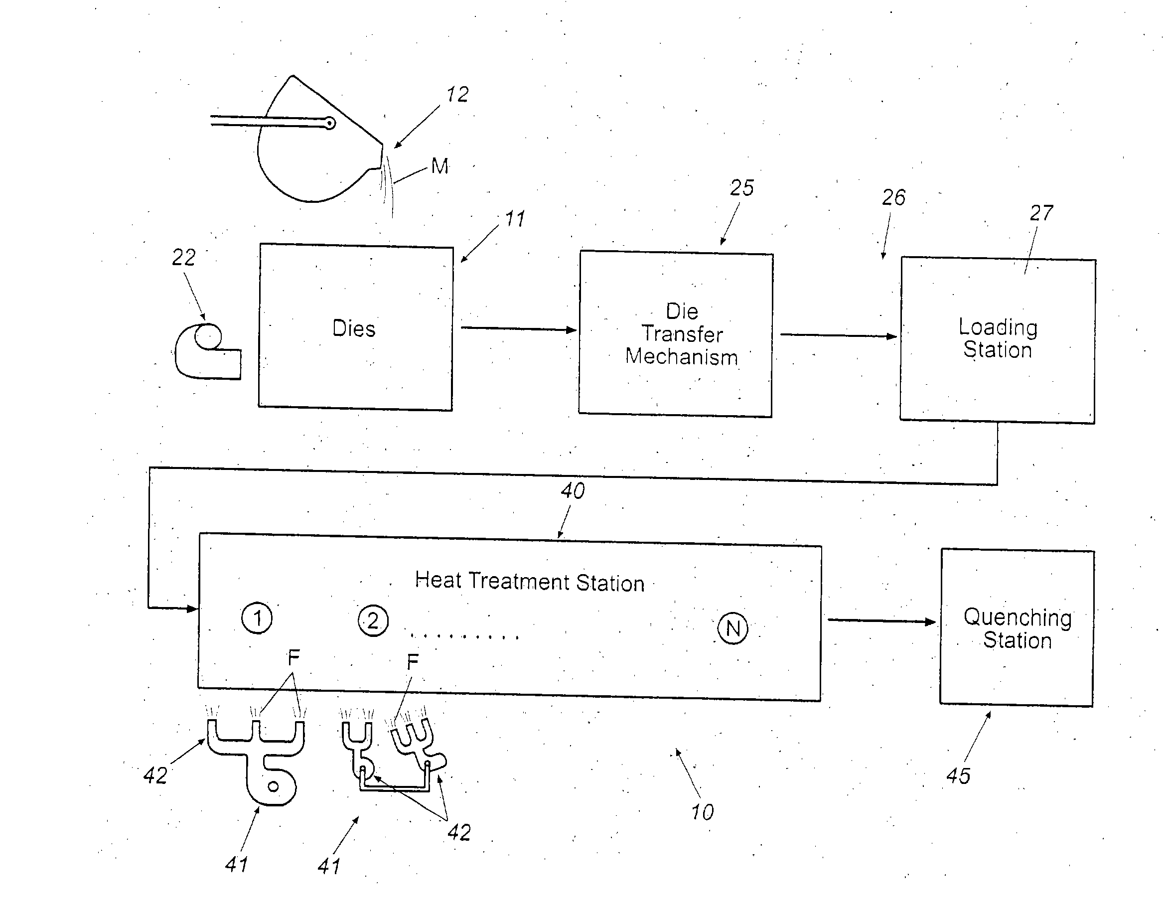
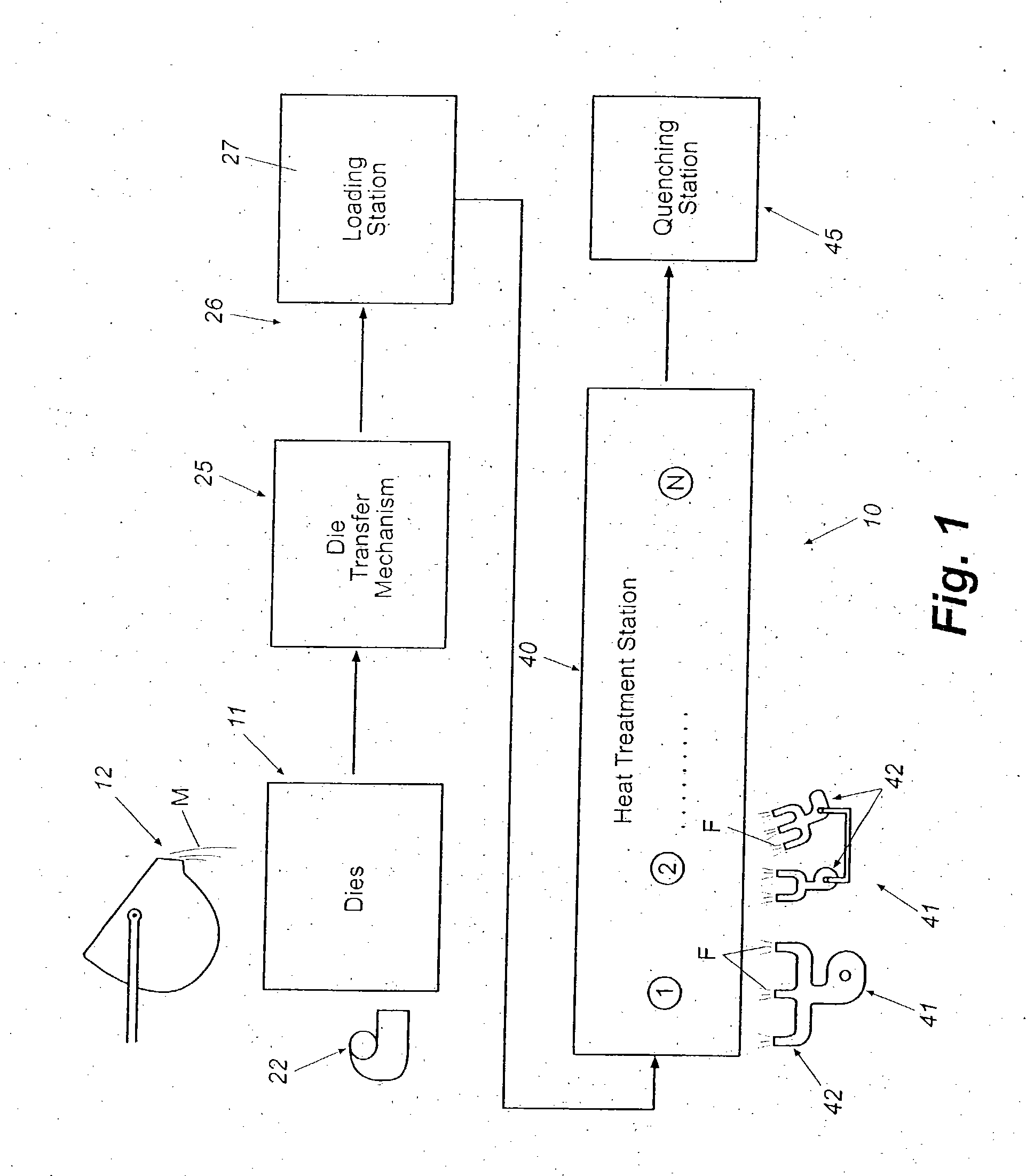
[0031] As indicated in FIG. 1, once the molten metal or metallic alloy has been poured into the mold and has at least partially'solidified into a casting, the mold and casting generally are removed from the pouring station 12 by a mold transfer mechanism 25, and are transferred to a loading station 26. The mold transfer mechanism can include a die transfer robot (not shown), winch or other type of conventionally known transfer mechanism for moving the molds from the pouring station to the loading station located in close proximity to the pouring station. In the invention, after the molten metal M has solidified within the mold to form the casting, the casting 13 (FIG. 3) is removed from its mold 11 prior to or at the loading station 26 (FIG. 1), such as by a robotic arm or similar mechanism, and is placed within a saddle 27 in a predefined, indexed position with its x, y, and z coordinates known. As a result, the core apertures 21 (FIG. 3) of the castings likewise are oriented or al...

embodiment 200

[0069]FIGS. 10A and 10B illustrate still a further embodiment 200 of the present invention for the enhanced heat treatment and breakdown and removal of sand cores and / or sand molds from a series of castings 201. In this embodiment, a molten metal or metal alloy M (FIG. 10A) is poured into a mold, such as a cast iron or other permanent type die or a semi-permanent or precision sand mold 202 at a pouring or casting station 203. The molds generally include an internal cavity 204 in which the molten metal is received and solidified to form the casting 201 and in which a sand core 206 typically is provided for forming ports or other interior detail for the casting. Typically, the molds in this embodiment will also include a series of ports or mold access openings 207 that extend through the side walls 208 of the molds. These ports provide an access to the interior cavity or chamber 204, and thus the casting being formed therein, for direct application of heat to the castings while “in-mo...


PUM

PropertyMeasurementUnit
Temperatureaaaaaaaaaa
Pressureaaaaaaaaaa
Flow rateaaaaaaaaaa

Abstract

A system and method for heat treating castings and removing sand cores therefrom. The castings are initially located in indexed positions with their x, y, and z coordinates known. The castings are passed through a heat treatment station typically having a series of nozzles mounted in preset positions corresponding to the known indexed positions of the castings passing through the heat treatment station. The nozzles apply fluid to the castings for heat treating the castings and degrading the sand cores for removal from the castings.

Description

CROSS-REFERENCE TO RELATED APPLICATION [0001] This application is a continuation-in-part of U.S. patent application Ser. No. 10 / 066,383, filed Jan. 31, 2002, which claims the benefit of U.S. Provisional Application Ser. No. 60 / 266,357, filed, Feb. 2, 2001, and which is a continuation-in-part of U.S. patent application Ser. No. 09 / 665,354, filed Sep. 9, 2000, which is a continuation-in-part of U.S. patent application Ser. No. 09 / 627,109, filed Jul. 27, 2000 (now abandoned), which claims the benefit of U.S. Provisional Application Ser. No. 60 / 146,390, filed Jul. 29, 1999, U.S. Provisional Application Ser. No. 60 / 150,901, filed Aug. 26, 1999, and U.S. Provisional Application Ser. No. 60 / 202,741, filed May 10, 2000. This application further claims priority to U.S. Provisional Application Ser. No. 60 / 401,969, filed Aug. 8, 2002. TECHNICAL FIELD [0002] This invention generally relates to metallurgical casting processes, and more specifically to a method and apparatus for removal of a sand...

Claims


Application Information

Patent Timeline
IPC IPC(8): B22D27/00B22D27/04B22D29/00
CPCB22D29/00B22D29/003C21D9/0068C21D1/53C21D1/52
Inventor CRAFTON, SCOTT P.CRAFTON, PAUL M.KNOBLOCH, VOLKER R.LEWIS, JAMES L. JR.FRENCH, IANRUEGG, FRANZ
Owner CONSOL ENG
Learn More