Impeller components and systems
a technology of components and components, applied in the direction of machines/engines, mechanical equipment, liquid fuel engines, etc., can solve the problems of reducing the overall efficiency of the system, excessive turbulence, inefficient energy transfer, etc., and achieves the effect of increasing the increasing the flow rate, and increasing the overall viscous drag surface area
- Summary
- Abstract
- Description
- Claims
- Application Information
AI Technical Summary
Benefits of technology
Problems solved by technology
Method used
Image
Examples
example 2
Comparison of Impeller Assembly with Standard Rotor
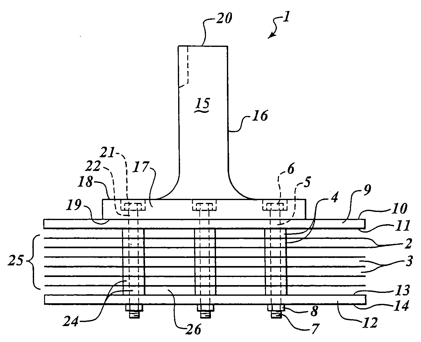
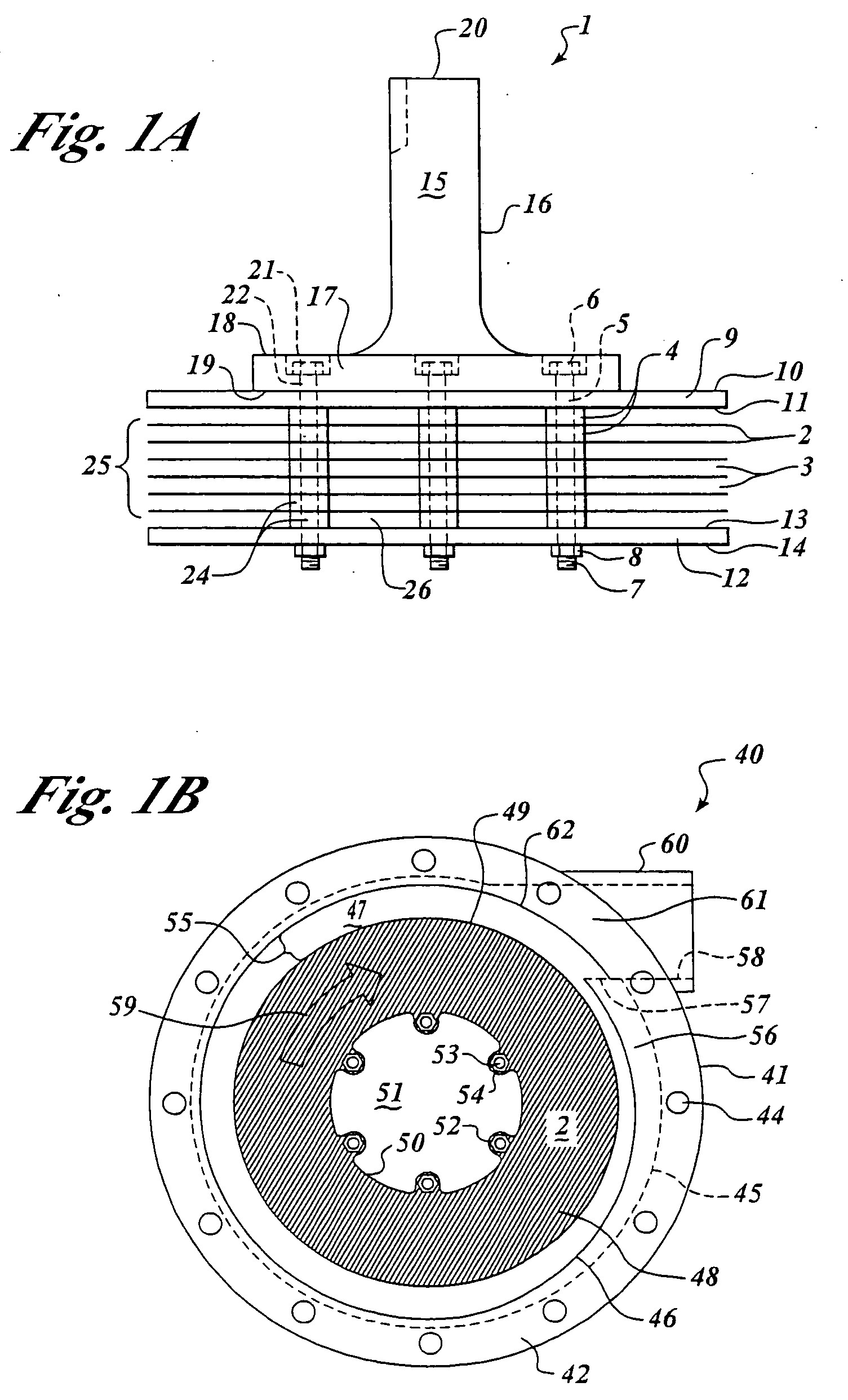
[0128] A controlled comparison of a standard rotor and an impeller assembly of the present invention was performed. Two 115 V, ½ hp pump motors (Dayton model # 3K380) were used in this study. One pump was fitted with a conventional rotor pump head (Grainger model #4RH42) having a 3.375″ diameter and a rotor depth of ⅜″, the other pump was fitted with an impeller assembly of the present invention having a 3.375″ diameter, but a 2″ rotor depth. Therefore, all motors, bases, plumbing, valves and the like were identical. With valves shut and pumps running, both systems used 7.7 amps. Below is a comparison of the two systems.
Comparison of ConventionalStandardImpellerRotor to Impeller AssemblyRotorAssemblyPressure: Valves shut17psi19psiOne Valve Open10psi13psiBoth Valves Open—10psiGallons per minute (+ / − 5%)24.630One Valve OpenGallons per minute (+ / − 5%)—48Both Valves OpenAmp Readings While Pumping8.9amps10.3amps
[0129] Further analysis...
example 3
Comparison of Impeller Assembly Centrifugal Pump with Standard Centrifugal Pump Having a Bladed Impeller
[0130] Several short-term and long-term tests comparing centrifugal pumps (0.5 HP and 1.5 HP) having an impeller assembly of the present invention with standard 0.5 and 1.5 HP centrifugal pumps having a bladed impeller were completed. The tests confirmed that conventional bladed impeller pumps suffer efficiency losses when operated at lower than 50% of maximum system pressure. For example, current consumption went flat when the conventional 1.5 HP centrifugal pump operated under 18 psi (50%). The conventional 1.5 HP centrifugal pump was not usable at pressures under 18 psi and wasted energy. The 0.5 HP centrifugal pump incorporating the impeller assembly of the present invention performed well, providing durability and silent operation. Even when operated at pressures of 2.45 psi, the output water was clear. The conventional bladed impeller pump produced aeration at 8 psi and was...
example 4
Impeller Assembly Pump for Marine Propulsion Applications
[0137] An impeller assembly of the present invention comprising 16 discs having an inter-disc spacing of 0.050 inch to make an array 1.5 inches thick and 6 inches in diameter was incorporated in a standard 9 HP outboard motor (the “test motor”). In this embodiment, the pump replaces the propeller and is mounted in an enclosed condition, which greatly reduces operational hazards to the operators, their guests and equipment, and the marine environment. Additionally, the outboard motor incorporating the impeller assembly of the present invention was not as sensitive to RPM as the conventional propeller-driven motor and operated substantially more efficiently. In the test environment, the test motor operated at 5000 RPM with no aeration of the propelling fluid. The conventional propeller motor experienced large losses during operation at over 2800 RPM as a result of cavitation, resulting in serious performance limitations in both...
PUM
 Abstract
Description
Claims
Application Information
 - R&D
- Intellectual Property
- Life Sciences
- Materials
- Tech Scout
- Unparalleled Data Quality
- Higher Quality Content
- 60% Fewer Hallucinations
Browse by: Latest US Patents, China's latest patents, Technical Efficacy Thesaurus, Application Domain, Technology Topic, Popular Technical Reports.
© 2025 PatSnap. All rights reserved.Legal|Privacy policy|Modern Slavery Act Transparency Statement|Sitemap|About US| Contact US: help@patsnap.com


