
Battery charger capable of accurately detecting battery temperature for full charge determination

a battery charger and accurate technology, applied in the field of battery chargers, can solve the problem that the battery temperature signal does not exhibit an accurate temperature, and achieve the effect of accurate full charge determination

Inactive Publication Date: 2005-01-27
HITACHI KOKI CO LTD
View PDF1 Cites 24 Cited by
  • Summary
  • Abstract
  • Description
  • Claims
  • Application Information

AI Technical Summary

Benefits of technology

[0009] In view of the foregoing, it is an object of the invention to provide a battery charger that eliminates the aforementioned drawbacks accompanying the conventional battery chargers and ensures accurate full charge determination even if contact conditions between the battery pack terminal and the charger terminal are degraded due to secular change.
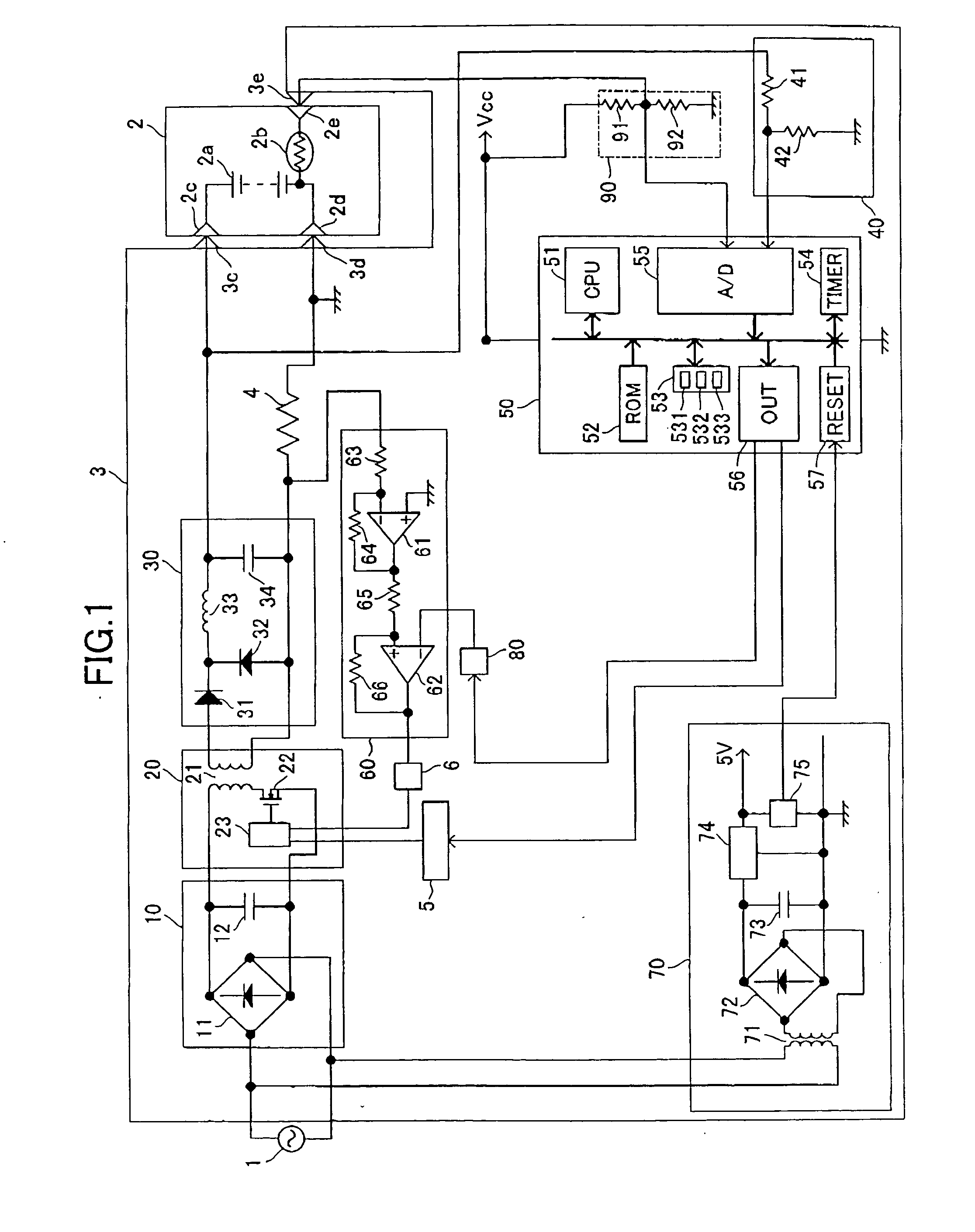
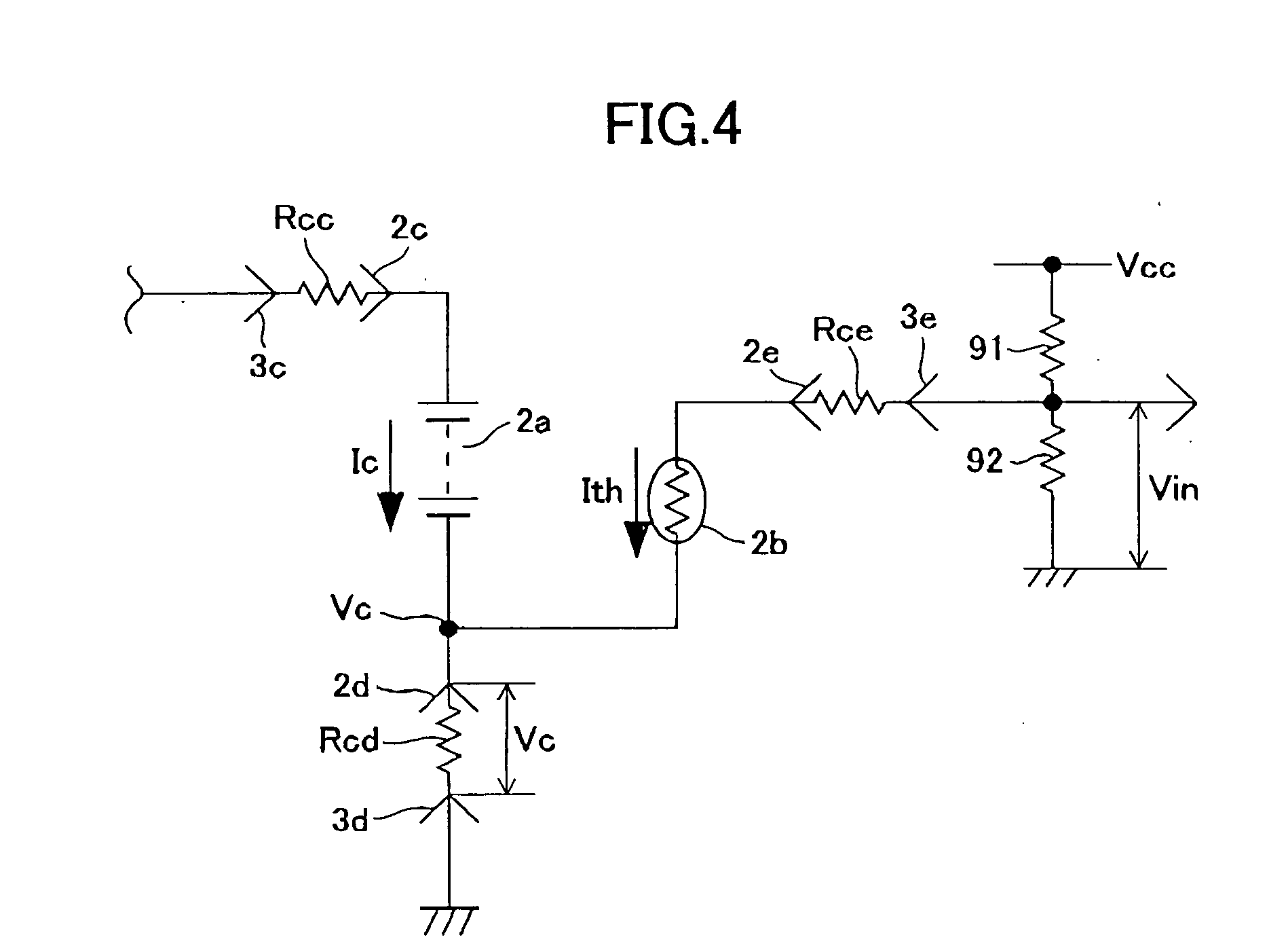
[0010] In order to achieve the above and other objects, there is provided a battery charger for charging a battery pack. The battery pack has a battery, a temperature sensor for sensing a temperature of the battery, and a battery terminal. Basically, the battery charger includes a charger terminal, a charge current generating circuit, a battery temperature detector, and a controller. The battery terminal is connected to the charger terminal when the battery is charged. The charge current generating circuit generates a charge current for charging the battery. The battery temperature detector detects a temperature of the battery while cooperating with the temperature sensor and outputs a temperature signal indicative of the temperature of the battery. The controller is supplied with the temperature signal from the battery temperature detector, corrects the is temperature signal, and provides a corrected temperature signal. The corrected temperature signal is substantially free from influence of contact resistance yielded in a contact portion of the battery terminal and the charger terminal.

Problems solved by technology

The battery temperature signal does not exhibit an accurate temperature of the battery if influenced by the contact resistance.

Method used


Image

  • Battery charger capable of accurately detecting battery temperature for full charge determination
  • Battery charger capable of accurately detecting battery temperature for full charge determination
  • Battery charger capable of accurately detecting battery temperature for full charge determination

Examples


Embodiment Construction

[0027] A preferred embodiment of the invention will be described while referring to the accompanying drawings.

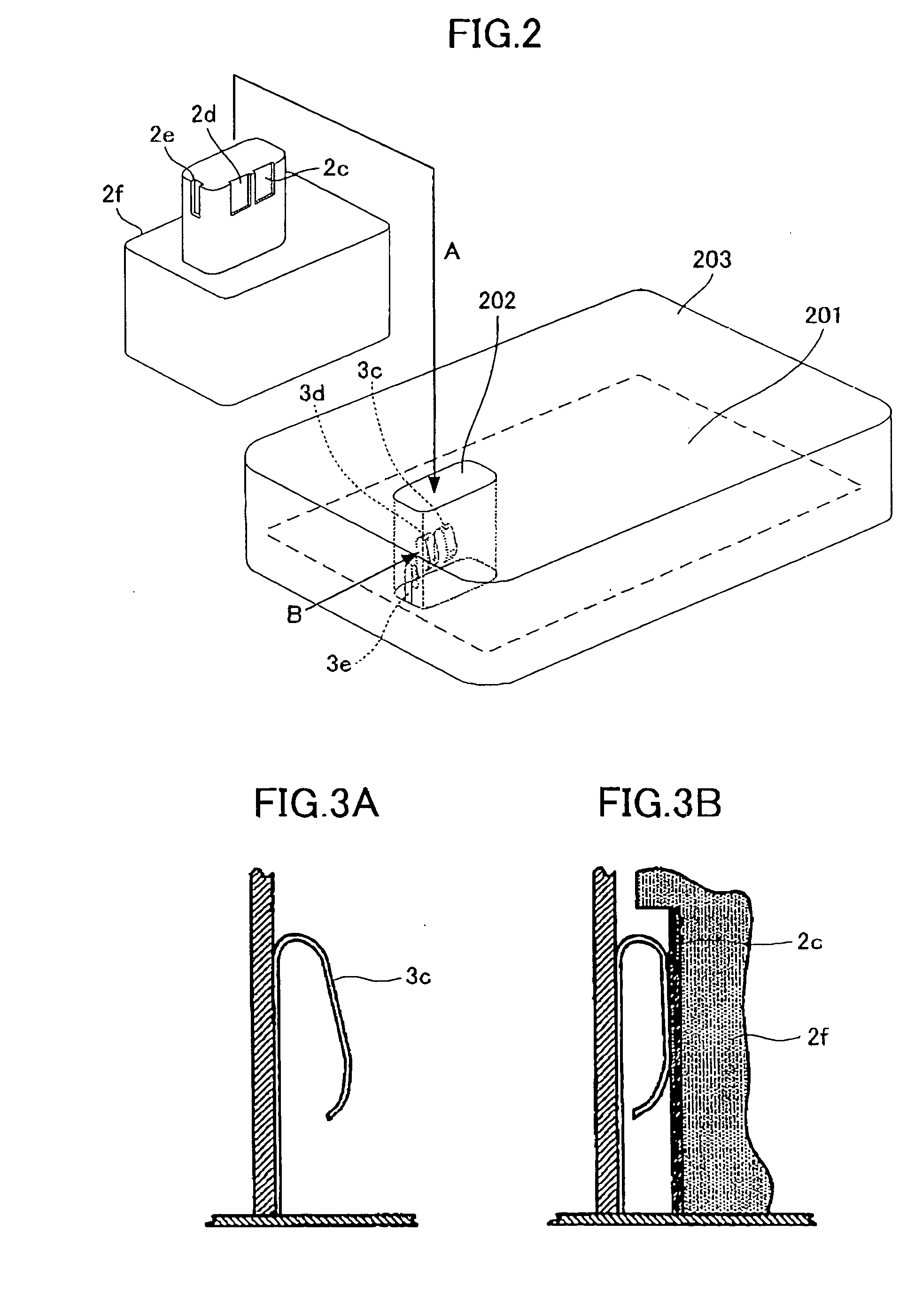
[0028]FIG. 1 shows an electrical circuit arrangement of a battery charger and a battery pack according to the preferred embodiment of the invention. As shown, the battery pack 2 includes a chargeable battery 2a, and a temperature sensor 2b. The battery 2a is composed of a plurality of battery cells connected in series. The temperature sensor 2b is disposed adjacent to or in contact with the battery 2a. A thermistor is, for example, used as the temperature sensor 2b. The battery pack 2 has a positive terminal 2c, a negative terminal 2d, and a temperature measurement terminal 2e amongst which the negative terminal 2d is used as a common terminal of the battery 2a and the temperature sensor 2b.

[0029] The battery charger 3 has a positive terminal 3c, a negative terminal 3d, and a battery temperature sensing terminal 3e which are connected to the positive terminal 2c, the negat...


PUM


Abstract

A full charge condition of a battery is determined based on a battery temperature gradient computed at every sampling time based on two values of detected battery temperatures. However, the battery temperature detected when the level of a charge current is switched does not exhibit an accurate temperature of the battery due to contact resistance existing in contact portion of a battery side terminal and a charger side terminal, resulting in inaccurate detection of the full charge condition. A microcomputer corrects the battery temperatures detected after the level of the charge current is switched and the full charge determination is made through computation of the battery temperature gradient using the corrected battery temperatures.

Description

BACKGROUND OF THE INVENTION [0001] 1. Field of the Invention [0002] The present invention relates to a battery charger for charging secondary batteries, such as nickel-cadmium batteries and nickel-hydrogen batteries. [0003] 2. Description of the Related Art [0004] Battery packs accommodating therein a nickel-cadmium battery or a nickel-hydrogen battery are used as power sources for a various kinds of portable devices, such as a cordless power tool. The battery pack for the cordless power tool typically accommodates a temperature sensor along with the battery. Battery temperatures detected by the temperature sensor are used to determine the full charge condition of the battery. [0005] Japanese Patent Application Publication No. HEI-6-113475 discloses a dT / dt detection method for determining the full charge condition using the detected battery temperatures. Specifically, while detecting the battery temperature at every sampling time with the use of the temperature sensor, a battery te...

Claims


Application Information

Patent Timeline
IPC IPC(8): H02J7/10H01M10/44H02J7/00H02J7/04
CPCH02J7/0091H02J7/007194
Inventor ARADACHI, TAKAOHARADA, HIDEKAZUISHIMARU, KENROUTAKANO, NOBUHIROTAKEDA, TAKESHI
Owner HITACHI KOKI CO LTD
Learn More