
Pen-sized telescoping electromagnet

a telescopic, magnet technology, applied in the direction of magnetic bodies, manufacturing tools, borehole/well accessories, etc., can solve the problems of insufficient strength to retrieve the desired item, small magnet employed, and often needed devices, etc., to achieve malleability, low breakage, and flexibility

Inactive Publication Date: 2005-01-27
ARROTTA GEORGE
View PDF28 Cites 15 Cited by
  • Summary
  • Abstract
  • Description
  • Claims
  • Application Information

AI Technical Summary

Benefits of technology

[0013] It is a general object of the invention to provide an improved magnetic pickup tool, which avoids the disadvantages of prior tools while affording additional structural and operating advantages.
[0015] Another important feature of the invention is the provision of an electromagnetic pickup tool which allows changes in the magnetic flux lines from extending from the tool by making the body primarily out of non-conductive material such as plastic or the like and allowing the tip or end cap to be interchangeable with variously shaped ones.
[0019] Still another feature of the invention is the provision of a pickup tool of the type set forth, which is of relatively simple and economical construction and readily manufactured.
[0021] These and other features of the invention are attained by providing a portable magnetic pickup tool comprising: A selectively elongated shaft having a handle end and a working end and a longitudinal axis extending there between, manually selectively variable magnetic means tipping the shaft at its working end for generating a magnetic field which extends there from, the handle being a telescoping substantially hollow non-conductive, resilient tubular structure resembling a combination of a ballpoint and telescoping pointer with small diameter insulated flexible copper wires therein selected due to their flexibility, malleability, and low breakage after repeated flexing.

Problems solved by technology

In many of such devices, the magnet employed is of small size for accessing small areas but is of insufficient strength to retrieve the desired item.
In addition, such devices are often needed in tight places surrounded by metal parts, which are also magnetically attractable.
Consequently, it is difficult to control the positioning of the magnet in such environments particularly since the flexible shaft enables the magnet to be drawn towards such surrounding metal parts.
However, these types of devices often do not provide a means for adjusting the length of the tool while being able to activate or deactivate the magnet and at the same time flex the tool anywhere along its entire length to better manipulate and pick up surrounding magnetically attractable materials.
Such known devices are large and cumbersome and require cords connected to large storage batteries or to a conventional source of AC current for the necessary power to operate.
One difficulty with such prior pickup tools solved by Slusar et al. is to control the flux lines of the magnet which extend laterally from the axis of the tool.
Thus, if the tool is being used in a location, such as in an automotive vehicle engine compartment or the like, with metallic walls or partitions, the magnet tends to be attracted to the metal walls or partitions, making it very difficult to reach the object to be retrieved so Slusar et al. added a push-button switch part to its “conductive” non-telescoping shaft for a portable tool.
However, such an arrangement has not heretofore been satisfactorily provided in portable electromagnetic pickup tools by using a variety of tip shapes in combination with a plastic or non-conductive “telescoping” housing offering manually selectively variable lengths and a push-button switch whereby the problem of the wall of the tool becoming magnetized, becoming attached at an undesirable location, not being able to be flexed to reach a location, or causing an electrical short is alleviated.

Method used


Image

  • Pen-sized telescoping electromagnet
  • Pen-sized telescoping electromagnet
  • Pen-sized telescoping electromagnet

Examples


Embodiment Construction

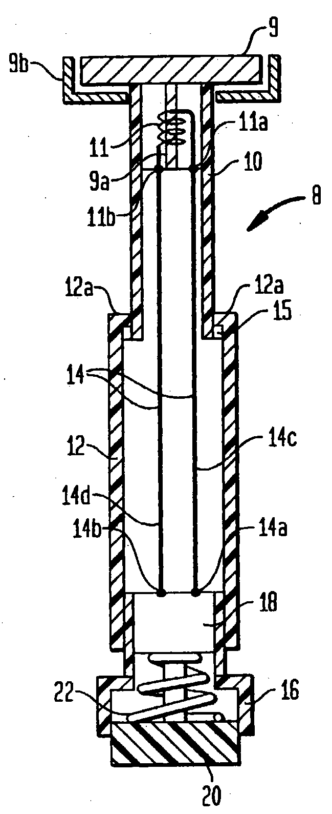
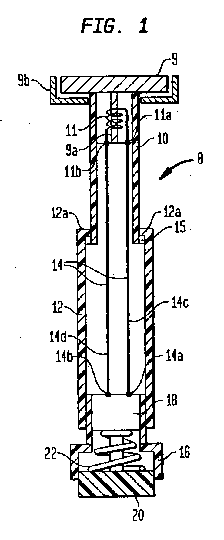
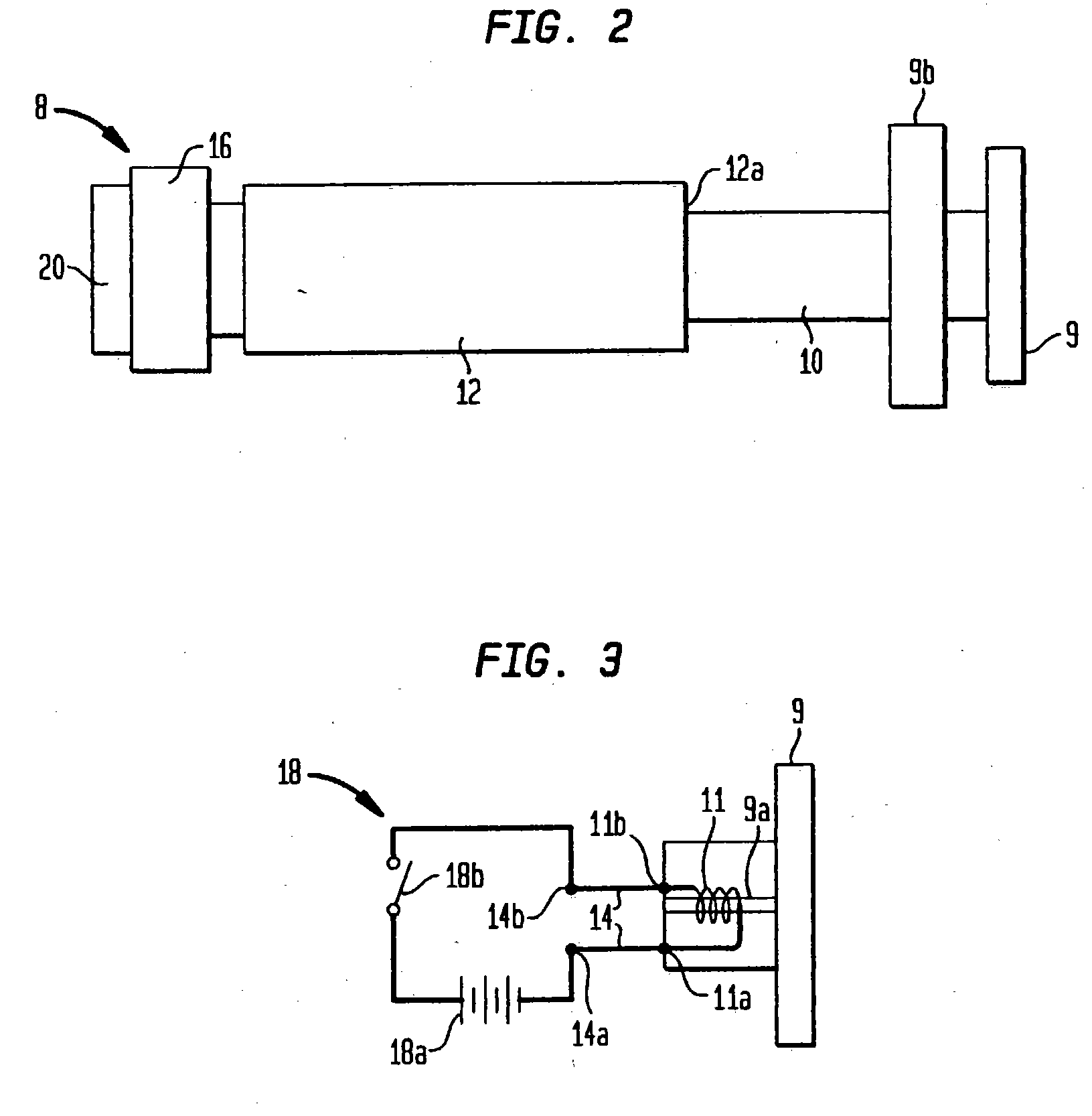
[0026] Referring to FIGS. 1 and 2, the assembly of the flexible telescoping electromagnetic tool 8 according to the present invention is illustrated. The electromagnetic tool 8 is constructed in the manner of a collapsible wand, ballpoint pen or flashlight with a selectively actuated electromagnet at a tip thereof. The actuated electromagnetic tip is used to attach, move, manipulate, and / or pick up magnetizable objects such as screws, bolts, nuts, nails, tacks, and the like. The electromagnetic tool 8 is made of an end member or end cap 9 capping a tubular end section 10.

[0027] The end cap 9 is formed of a magnetizable material such as a nickel iron alloy and has an integral extension 9a that is coated with an electrical insulator and wrapped with an inductor 11 having contacts 11a and 11b as shown in FIG. 1 and in the circuit diagram of FIG. 3. Alternatively, the inductor 11 may be made of wire having an electrically insulating coating; and then, the extension 9a may be uncoated. ...


PUM


Abstract

A flexible telescoping electromagnetic tool comprises an end cap formed of a magnetizable material and an end section formed of a non-magnetizable material. The end cap is connected to the end section. A tubular section is formed of a non-magnetizable material wherein the tubular section slidably receives the end section. An electrically conducting insert is disposed through the tubular section and through the end section. The conducting insert is electrically connected to a power supply. The module is attached to the distal end of the non-magnetizable tubular section. The electromagnetic tool also has a ring insert secured to the end section. The ring insert is formed of plastic and has a width that is greater than a diameter of the opening. The ring insert is attached inside said tubular section. The insert connects to an inductor. The inductor has two contacts and is near the end cap.

Description

PRIORITY DATE CLAIMED [0001] No priority date is claimed for this application. BACKGROUND OF THE INVENTION [0002] 1. Field of the Invention [0003] The invention relates to the location and retrieval of magnetically attractable objects using electromagnetic means disposed at an end of a flexible member. [0004] 2. Description of Prior Art [0005] Various magnetic pick-up devices for magnetically attractable items are known which include a flexible shaft for manipulating a magnet on the end of the shaft into an area, which is otherwise inaccessible. In many of such devices, the magnet employed is of small size for accessing small areas but is of insufficient strength to retrieve the desired item. In addition, such devices are often needed in tight places surrounded by metal parts, which are also magnetically attractable. Consequently, it is difficult to control the positioning of the magnet in such environments particularly since the flexible shaft enables the magnet to be drawn towards...

Claims


Application Information

Patent Timeline
IPC IPC(8): B25B9/00B25B11/00H01F7/20
CPCB25B9/00H01F2007/208H01F7/206B25B11/002
Inventor ARROTTA, GEORGE
Owner ARROTTA GEORGE
Learn More