Pair of seat rails for a vehicle seat

a vehicle seat and seat rail technology, applied in the field of seat rails for vehicle seats, can solve the problems of energy dissipation, weight and cost increase, and unnecessary reinforcement of the second seat rail, and achieve the effects of reducing the retransmission of force, optimizing the flow of force, and keeping manufacturing simpl

Inactive Publication Date: 2005-01-20
KEIPER GMBH & CO KG
View PDF9 Cites 9 Cited by
  • Summary
  • Abstract
  • Description
  • Claims
  • Application Information

AI Technical Summary

Benefits of technology

[0005] As a result of providing the hole between the mounting point and the interlocking section, the forces that are introduced in the event of a crash via the mounting point are concentrated (e.g., stress is concentrated in at least some of the material that surrounds and defines the hole) and thereby able to affect a purposeful deformation in the region of the hole. This deformation lowers a retransmission of force on this side of the vehicle seat, and thus makes the load distribution more equal between the two sides of the vehicle seat. This effects a reduction of the partial forces that act upon the interlocking section. Weight and cost increasing reinforcements of the second seat rail will then be unnecessary. Furthermore, still some energy will be dissipated in the event of a crash.
[0006] In a preferred embodiment, the hole is made in the shape of a slot, which concentrates the deformation at the ends of the slot. Preferably, the hole is straight and elongated in the longitudinal direction, which optimizes the flow of force, and keeps manufacturing simple. This allows accomplishment of a purposeful movement of the material from the center region of the hole transversely to the longitudinal direction of the slot-shaped hole. Preferably, the hole is formed in the adapter section, i.e., in the vicinity of the mounting point, and preferably below same, which provides a better protection of the other sections. In particular, in the case of an asymmetric rail profile, which is also subjected to an asymmetric load, it will be advantageous for the hole to extend transversely to the longitudinal direction only partially through the adapter section. For example, the hole can be provided only in one layer of two abutting layers that together form the adapter section.
[0007] A pair of seat rails made in accordance with the present invention is usable for all types of longitudinally adjustable vehicle seats for promoting an improved load distribution. The effect of the hole will, however, be greatest when the structural component arranged in the mounting point is rigidly mounted to the adapter section. An indentation in the rear edge of the first seat rail improves the protection against a cutting into the second seat rail by this relatively sharp-edged and very stiff seat rail end.
[0008] It is preferred for the hole to be proximate the rear edge of the first seat rail and for the hole to be shaped in a manner that at least partially defines an advantageous deformation which occurs in the end section of the first seat rail in the event of the crash of predetermined magnitude, or the like. It is preferred for the indentation in the rear edge of the first seat rail to advantageously enhance the deformation which occurs in the end section of the first seat rail as a result of the hole etc.

Problems solved by technology

Weight and cost increasing reinforcements of the second seat rail will then be unnecessary.
Furthermore, still some energy will be dissipated in the event of a crash.

Method used


Image

  • Pair of seat rails for a vehicle seat
  • Pair of seat rails for a vehicle seat

Examples


Embodiment Construction

[0013] The present invention now will be described more fully hereinafter with reference to the accompanying drawings, in which one of the embodiments of the invention is shown. Indeed, the invention may be embodied in many different forms and should not be construed as limited to the embodiment(s) set forth herein; rather, these embodiment(s) are provided so that this disclosure will satisfy applicable legal requirements. Like numbers refer to like elements throughout.

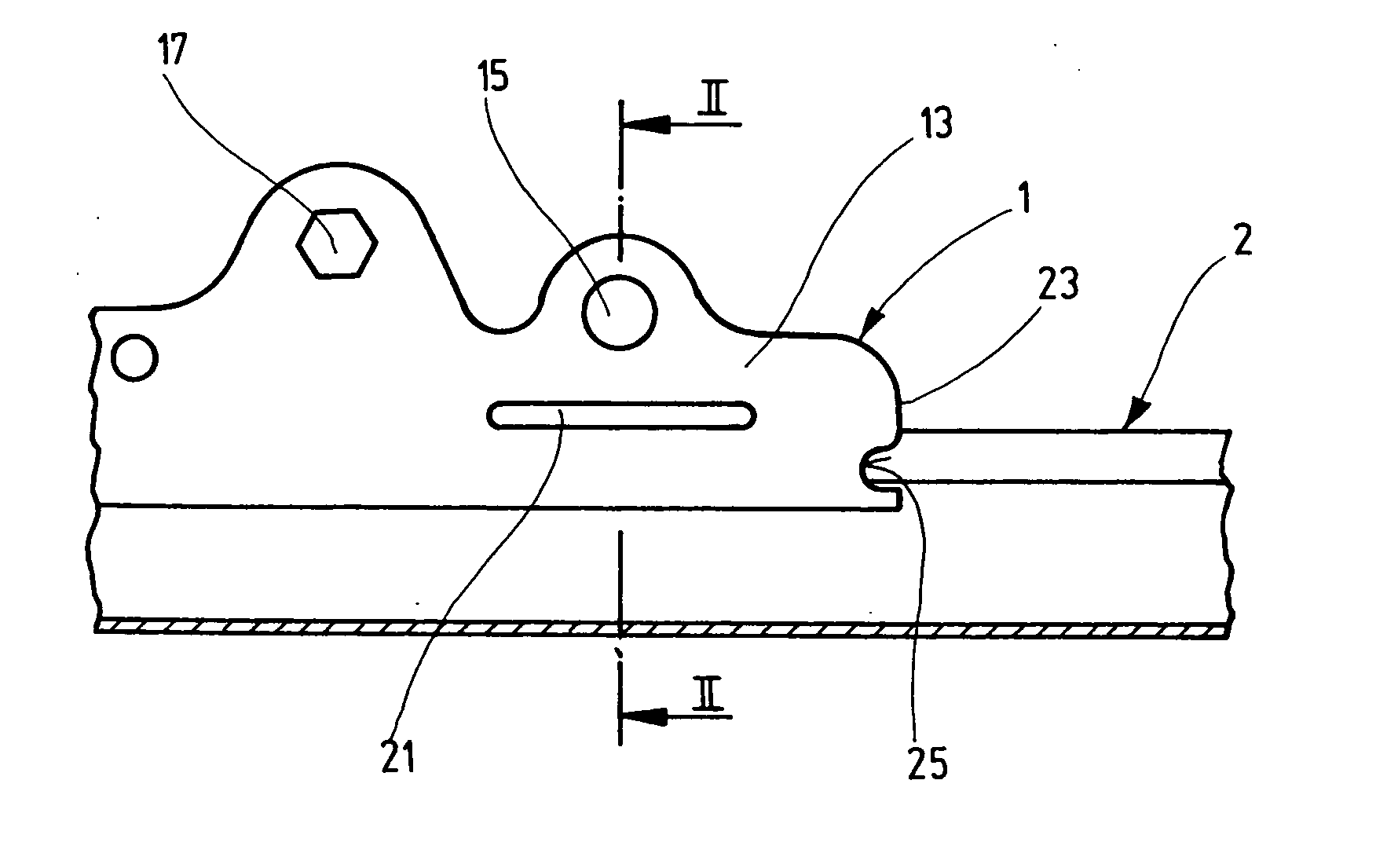
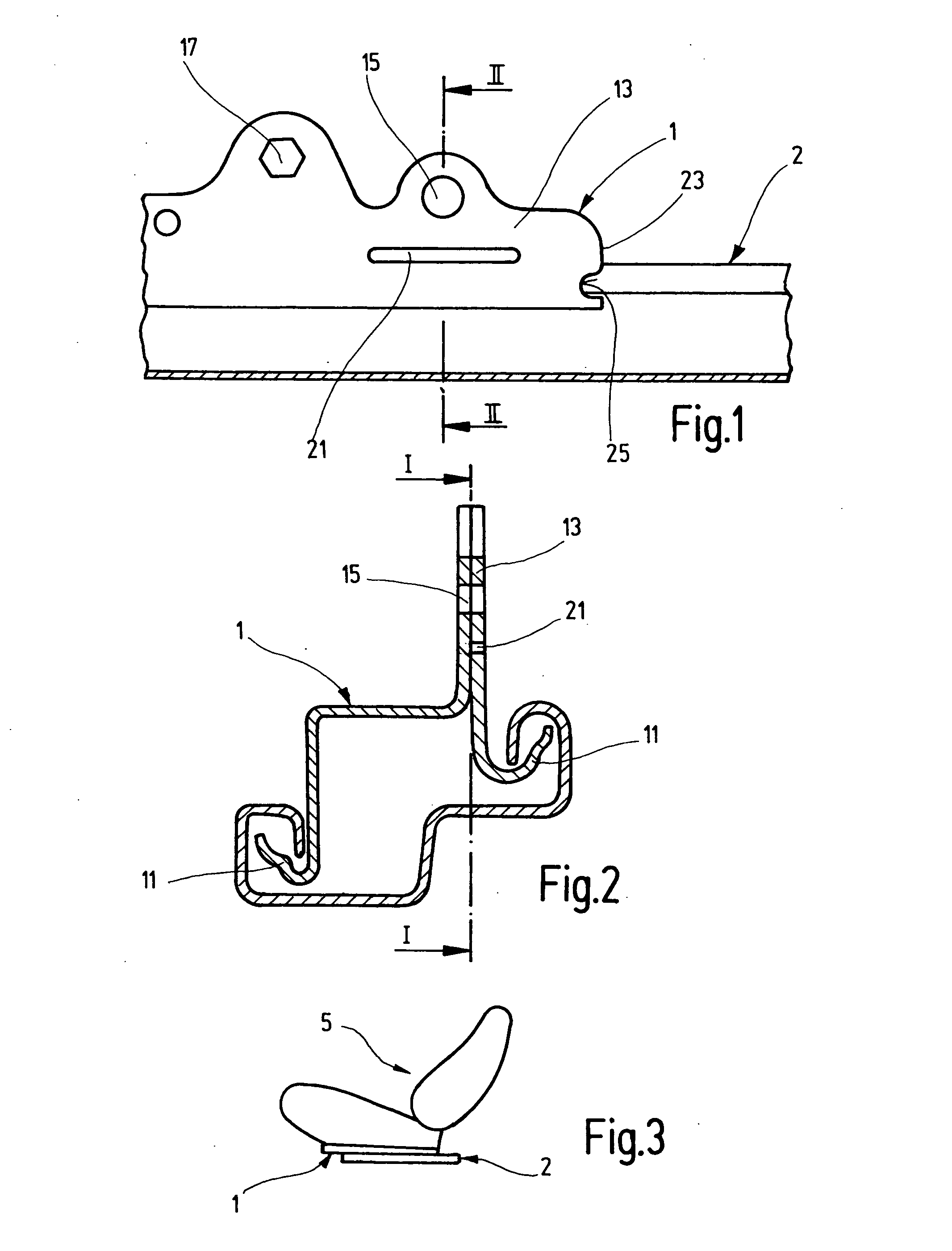
[0014] A first seat rail 1, which is constructed as an upper rail and used as a slide rail, is arranged in a known manner for displacement in the longitudinal direction in a second seat rail 2, which is constructed as a lower rail and used as a guide rail. The first seat rail 1 preferably carries a locking mechanism (not shown) for engaging at least the second seat rail 2 to releasably lock the seat rails 1 and 2 together and thereby prevent the first seat rail from sliding relative to the second seat rail. For examp...


PUM


Abstract

In a pair of seat rails for a vehicle seat, in particular for an automobile seat, with a first seat rail (1) and a second seat rail (2), with the first seat rail (1) being guided in the longitudinal direction for displacement in the second guide rail (2) and having at least one interlocking section (11) for interacting with the second seat rail (2) and an adapter section (13), which includes at least one mounting point (15) for arranging a structural component of the vehicle seat (5), a hole (21) is provided between the mounting point (15) and the interlocking section (21), and the hole is operative for operating advantageously in the event of a crash.

Description

BACKGROUND OF THE INVENTION [0001] The present invention relates to a pair of seat rails for a vehicle seat, in particular for an automobile seat, with the pair of seat rails including a first seat rail that is guided in a second seat rail for displacement in the longitudinal direction, and the first seat rail including an adapter section and at least one interlocking section for interacting with the second seat rail, with the adapter section including at least one mounting point for receiving a structural component of the vehicle seat. [0002] In the case of a known pair of seat rails of the type described above, and which is arranged on the side of the vehicle seat with the belt lock, reinforcement is provided, in particular for the second seat rail at the rear end (or in another critical region). This reinforcing prevents, in the event of a crash or in the case of a belt equivalent load test in the foremost position, the first seat rail from cutting off the second rail with its in...

Claims


Application Information

Patent Timeline
Patent Type & Authority Applications(United States)
IPC IPC(8): B60N2/07B60N2/427
CPCB60N2/42709B60N2/0705
Inventor DILL, THOMASBRAUN, DIETERMUHLBERGER, JOACHIMTEUFEL, INGOROTH, STEFAN
Owner KEIPER GMBH & CO KG
Why Eureka
Try Eureka