
Vehicle control method and apparatus

a vehicle control and vehicle technology, applied in the field of vehicle control, can solve the problems of complete bypass of the vehicle control system, conflicting manual requests received by the suspension subsystem, and complicated and confusing, and achieve the effect of maximizing the control of the vehicle driving mod

Active Publication Date: 2005-01-06
JAGUAR LAND ROVER LTD
View PDF4 Cites 154 Cited by
  • Summary
  • Abstract
  • Description
  • Claims
  • Application Information

AI Technical Summary

Benefits of technology

[0012] The invention provides an improved apparatus and method for controlling the vehicle control system by avoiding unplanned combinations of subsystem configuration modes and minimizing the transition time when changing between subsystem configuration modes.
[0017] The invention may then facilitate a method of controlling a suspension subsystem ride height that is most suitable for driving on a respective surface wherein if it appears that the driver has made a deliberate choice to put the vehicle in a condition that is also likely to be giving a benefit to the driver, such as off-road ride height selection, then this condition will be maintained when a driving mode change is made.
[0023] Preferably one of the subsystems comprises a yaw control system which is arranged to control vehicle yaw, and said plurality of subsystem configuration modes allow different levels of divergence of said vehicle yaw from an expected yaw.
[0035] The method thus enables controlling a plurality of vehicle subsystems within a motor vehicle in a manner suitable for a respective driving surface and minimizing unplanned combinations, by arranging for all driving modes being started within each subsystem simultaneously, by allowing the vehicle mode controller to request a driving mode change only when all the subsystems indicate that they are available for a change, and by allowing the vehicle mode controller to change to an available mode if one or more subsystems do not respond to the demand for a driving mode change within a short period of time, such as 1000 milliseconds.
[0036] Optionally, a device for conveying advice to the driver may be provided. This device can help the driver to maximize control of the vehicle driving modes when responding to a broad range of surfaces.

Problems solved by technology

Unless the driver is very experienced, this can become complicated and confusing.
It is possible that this manual request received by the suspension subsystem might be in conflict with a current or future command by the vehicle control system requiring a different suspension subsystem configuration.
Unfortunately, these simple solutions often result in a complete bypass of the vehicle control system and fail to take advantage of the benefits associated with optimizing for the terrain.
However, vehicle control systems will sometimes confront circumstances where a subsystem cannot change to the pre-defined subsystem configuration mode requested.
Such a situation might occur when the driver manually overrides a control (e.g., the automatic transmission gearbox is in manual shifting, so the system is unable to select the appropriate shift map) or for safety reasons (e.g., the vehicle speed exceeds a threshold limit upon which it will not allow for raising the ride height).
Therefore, the system may have to refuse the request to change to ‘A’ mode.
Or, perhaps even more problematic is the need to retract the demand for the change to ‘A’ mode from those subsystems that have already implemented the change from the current mode.
The fact that some of the subsystems might be partially changing raises the possibility of unplanned combinations of subsystem configuration modes.
Furthermore, when the vehicle control system determines that it is necessary to perform a mode change, due to the fact that control commands are issued over a serial network, the network can sometimes introduce variable latency times such that each subsystem receives the signal to change modes at different times. This latency translates into a window of time in which the vehicle is not at its' optimal performance level.

Method used


Image

  • Vehicle control method and apparatus
  • Vehicle control method and apparatus
  • Vehicle control method and apparatus

Examples


first embodiment

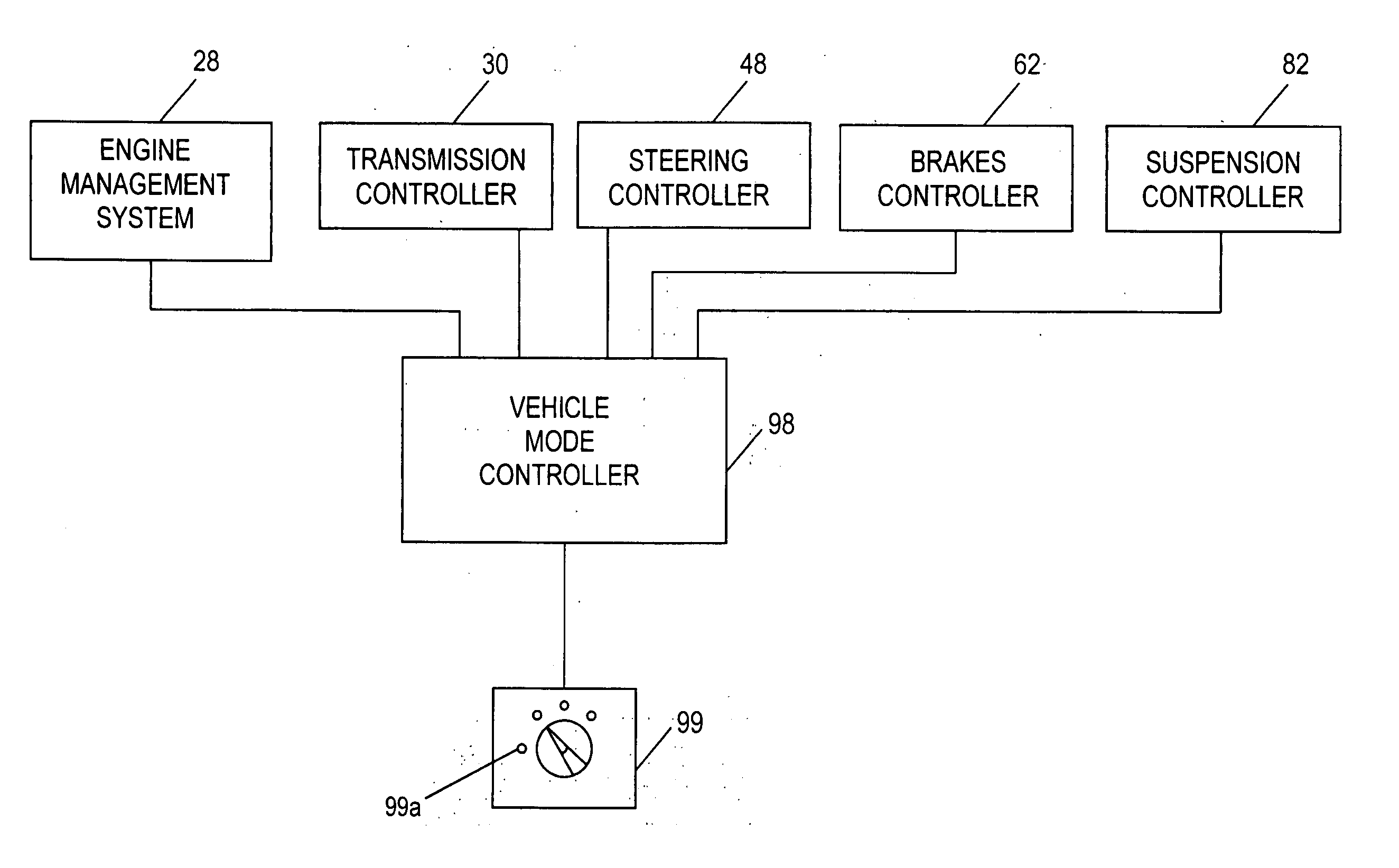
[0069] Referring to FIG. 4, the invention including all of the subsystem controllers, that is the engine management system 28, the transmission subsystem controller 30, the steering subsystem controller 48, the brakes subsystem controller 62 and the suspension subsystem controller 82 are all connected to a vehicle mode controller 98 which integrates the configuration modes of operation of each of the subsystem controllers.

[0070] The vehicle mode controller 98 collects input regarding the vehicle driving terrain, vehicle performance, and the state of the vehicle subsystems into its memory. The vehicle mode controller 98 determines the appropriate control command for the driving surface and issues the command to all of the subsystem controllers. The subsystems, and each of the functions described above, are controlled so as to provide a number of driving modes for the vehicle. Each of the driving modes corresponds to a particular driving condition or set of driving conditions, and in ...

second embodiment

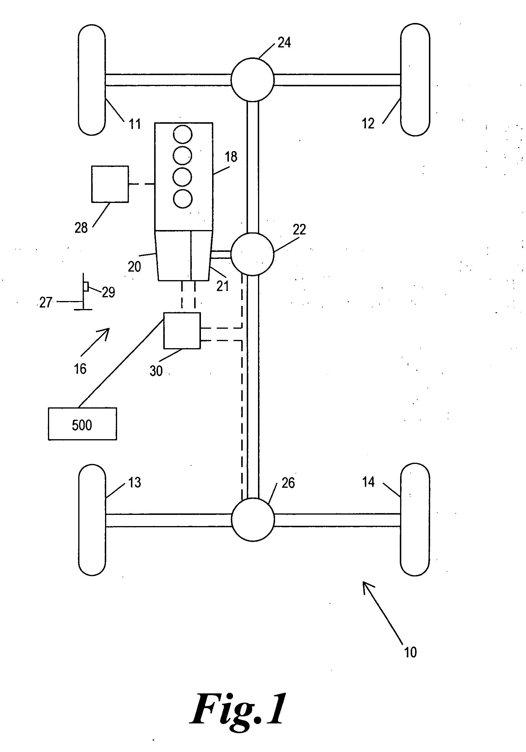
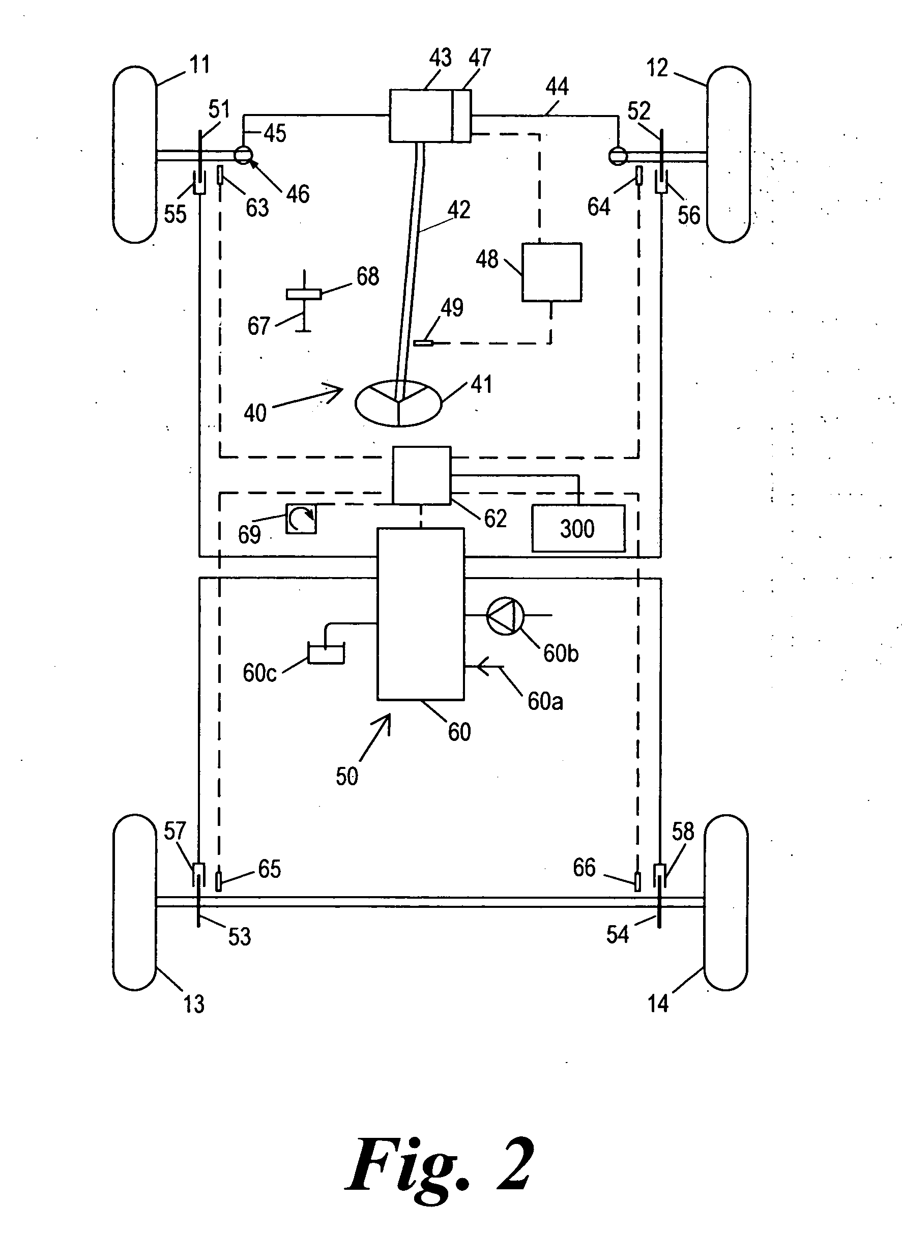
[0077] Referring to FIG. 10, the invention is shown including all of the subsystem controllers, that is the engine management system 28, the transmission subsystem controller 30, the steering subsystem controller 48, the brakes subsystem controller 62 and the suspension subsystem controller 82 are all connected to a vehicle mode controller 98 which integrates the configuration modes of operation of each of the subsystem controllers. Additionally, one or more manual subsystem control means such as switches 300, 400, and 500 are connected to the brake, suspension, and transmission subsystem controllers respectively. The manual switches allow the driver to manually request each subsystem to perform specific functions such as changing the ride height of the vehicle by adjusting the air suspension subsystem. Each switch would be located inside the driving compartment of the vehicle.

[0078] We can further describe the second embodiment of the invention when either the driving mode is chang...

third embodiment

[0095] In FIG. 12, all of the subsystem controllers, that is the engine management system 28, the transmission subsystem controller 30, the steering subsystem controller 48, the brakes subsystem controller 62 and the suspension subsystem controller 82 are all connected to a vehicle mode controller 98 which controls the configuration modes of operation of each of the subsystem controllers. Additionally, manual subsystem control means such as switches 300, 400, and 500 are connected to the brake, suspension, and transmission subsystem controllers respectively, and a means for providing driving advice 200 is connected to the vehicle mode controller. The driving advice apparatus 200 which may be integrated into the instrument console, is used extensively by the vehicle control system to display driving mode related vehicle information and driving advice related to optimizing the vehicle subsystems integrating the manual subsystem control means.

[0096]FIG. 9 further describes a preferred ...


PUM


Abstract

A vehicle mode controller, a driving mode collecting means, and a plurality of subsystem controllers including an engine management system, a transmission controller, a steering controller, a brakes controller and a suspension controller, provide an improved system and method of operating a vehicle control system in a host vehicle in a manner suitable for a respective driving surface in a plurality of different off-road surfaces and terrains such as might be encountered when driving off-road. An improved method is provided for controlling a vehicle control system by avoiding unplanned combinations of subsystem configuration modes and minimizing the transition time when changing between subsystem configuration modes.

Description

FIELD OF THE INVENTION [0001] The present invention relates to the control of vehicles, in particular to the coordinated control of a number of subsystems of a vehicle. TECHNICAL BACKGROUND [0002] Various systems are known in which operation of various subsystems of a vehicle can operate in different configuration modes so as to suit different conditions. For example, automatic transmissions can be controlled in sport, winter, economy and manual configuration modes in which the changes between gear ratios and other subsystem control parameters are modified so as to suit the prevailing conditions or the taste of the driver. Air suspensions are known with on-road and off-road configuration modes. Stability control systems can be operated at reduced activity so as to give the driver more direct control over the operation of the vehicle. Power steering systems can be operated in different configurations modes where the level of assistance is at different levels or varies in different wa...

Claims


Application Information

Patent Timeline
Patent Type & Authority Applications(United States)
IPC IPC(8): B60G17/00B60K28/10B60R16/02B60T8/00B62D6/00B62D37/00G05B19/042G06F17/00
CPCB60W10/06B60W10/10B60W10/18B60W10/20G05B2219/2637B60W30/182B60W50/045B60W2050/0096B60W10/22B60W30/00G05B19/0421
Inventor BERRY, ADRIANSLANEY, TIMBREUGELMANS, ADRIEPRINS, JANJONES, DEREKMOORE, NICKCLARE, DAVID ANDREWARMSTRONG, DAVIDCOOK, RICHARDPARSONS, KEITH GARY REGINALDANKER, SAMINCH, DAVIDDICKEN, SCOTTGUEST, PHILCOTTA, ANDREW
Owner JAGUAR LAND ROVER LTD
Learn More