Electro-kinetic air transporter and conditioner devices with features that compensate for variations in line voltage

Inactive Publication Date: 2004-12-16
SHARPER IMAGE ACQUISITION
View PDF99 Cites 45 Cited by
  • Summary
  • Abstract
  • Description
  • Claims
  • Application Information

AI Technical Summary

Benefits of technology

[0023] The upper surface 103 of the housing 102 includes a user-liftable handle member 112 to which is affixed a second array 240 of collector electrodes 242. The housing 102 also encloses a first array of emitter electrodes 230, or a single first emitter electrode shown here as a single wire or wire-shaped electrode 232. (The terms "wire" and "wire-shaped" shall be used interchangeably herein to mean an electrode either made from a wire or, if thicker or stiffer than a wire, having the appearance of a wire.) In the embodiment shown, handle member 112 lifts second array electrodes 240 upward causing the second electrode to telescope out of the top of the housing and, if desired, out of unit 100 for cleaning, while the first electrode array 230 remains within unit 100. As is evident from the figure, the second array of electrodes 240 can be lifted vertically out from the top 103 of unit 100 along the longitudinal axis or direction of the elongated housing 102. This arrangement with the second electrodes removable from the top 103 of the unit 100, makes it easy for the user to pull the second electrodes 242 out for cleaning. In FIG. 2B, the bottom ends of second electrodes 242 are connected to a member 113, to which is attached a mechanism 500, which includes a flexible member and a slot for capturing and cleaning the first electrode 232, whenever handle member 112 is moved upward or downward by a user. The first and second arrays of electrodes are coupled to the output terminals of ion generating unit 160.

Problems solved by technology

Often these devices are somewhat cumbersome, and have the size and bulk of a small filing cabinet.
Although such fan-powered devices can reduce or destroy microorganisms, the devices tend to be bulky, and are not necessarily silent in operation.

Method used


Image

  • Electro-kinetic air transporter and conditioner devices with features that compensate for variations in line voltage
  • Electro-kinetic air transporter and conditioner devices with features that compensate for variations in line voltage
  • Electro-kinetic air transporter and conditioner devices with features that compensate for variations in line voltage

Examples


Embodiment Construction

of Air-Transporter-Conditioner System with Germicidal Lamp

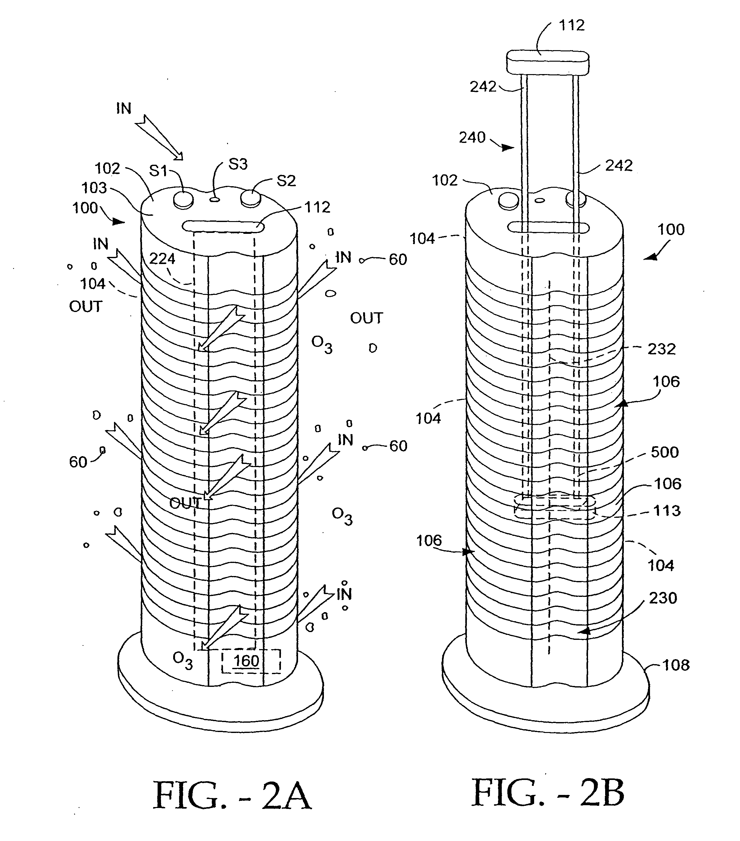
[0027] FIGS. 3A-6 depict various embodiments of the device 200, with an improved ability to diminish or destroy microorganisms including bacteria, germs, and viruses. Specifically, FIGS. 3A-6 illustrate various preferred embodiments of the elongated and upstanding housing 210 with the operating controls located on the top surface 217 of the housing 210 for controlling the device 200.

[0028] FIGS. 3A-3E

[0029] FIG. 3A illustrates a first preferred embodiment of the housing 210 of device 200. The housing 210 is preferably made from a lightweight inexpensive material, ABS plastic for example. As a germicidal lamp (described hereinafter) is located within the housing 210, the material must be able to withstand prolonged exposure to class UV-C light. Non "hardened" material will degenerate over time if exposed to light such as UV-C. By way of example only, the housing 210 maybe manufactured from CYCLOLAC.RTM. ABS Resin, (material de...


PUM


Abstract

Systems and methods are provided for compensating for variations in line voltages the power an electro-kinetic air transporter and conditioner device. The electro-kinetic air transporter and conditioner device includes a high voltage generator that provides a potential difference between at least one emitter electrode and at least one collector electrode. The high voltage generator is driven by both a DC voltage obtained from an AC voltage source, and a low voltage pulse signal. The DC voltage is stepped down to produce a voltage sense signal indicative of a level of AC voltage source. The voltage sense signal is monitored. At least one of a pulse width, duty cycle and frequency of the low voltage pulse signal is adjusted, based on the monitored voltage sense signal, in order to substantially maintain the potential difference at a desired level.

Description

PRIORITY CLAIM[0001] This application is a divisional of and claims priority to U.S. patent application Ser. No. 10 / 625,401 (Attorney Docket No. SHPR-01361USB), entitled "ELECTRO-KINETIC AIR TRANSPORTER AND CONDITIONER DEVICES WITH ENHANCED ARCING DETECTION AND SUPPRESSION FEATURES," filed Jul. 23, 2003, which claims priority under 35 U.S.C. 119(e) to U.S. Provisional Patent Application No. 60 / 477,980 (Attorney Docket No. SHPR-01361US1), filed Jun. 12, 2003, entitled "ELECTRO-KINETIC AIR TRANSPORTER AND CONDITIONER DEVICES WITH ENHANCED ARCING DETECTION AND SUPPRESSION FEATURES," each of which is incorporated herein by reference.[0002] The present invention relates generally to devices that transport and / or condition air.[0003] FIG. 1 depicts a generic electro-kinetic device 10 to condition air. Device 10 includes a housing 20 that typically has at least one air input 30 and at least one air output 40. Within housing 20 there is disposed an electrode assembly or system 50 comprising...

Claims


Application Information

Patent Timeline
IPC IPC(8): A61L9/015A61L9/22C01B13/11F24F1/02F24F3/16F24F11/02
CPCA61L9/015A61L9/22C01B13/11C01B13/115B03C3/68C01B2201/22C01B2201/90F24F3/166F24F2003/1682C01B2201/12F24F8/30F24F8/192Y02A50/20
Inventor LAU, SHEK FAI
Owner SHARPER IMAGE ACQUISITION
Why Eureka
Try Eureka