
Built-in self-test for digital transmitters

a self-testing and digital transmitter technology, applied in the field of built-in self-testing for digital transmitters, can solve the problems of large memory and processing power requirements, radio modulators are often subject to extreme environmental conditions, and testing is typically not required

Inactive Publication Date: 2004-09-30
ARRAYCOMM INC
View PDF14 Cites 30 Cited by
  • Summary
  • Abstract
  • Description
  • Claims
  • Application Information

AI Technical Summary

Benefits of technology

"The present invention provides a built-in self-test for digital radio modulators or other devices. The test can be managed by a master control unit or a controller in the physical layer processor. The test uses a cyclic or recursive algorithm, such as a linear feedback shift register, to process the modulator output. The test can be run autonomously without interfering with higher layer processes. The invention allows for complex digital processing engines to be tested automatically and autonomously using a minimum of memory and processing resources. It also allows for testing in the field and in real-time, reducing the need for expensive external test equipment. The invention provides a solution for testing digital radio modulators and ensuring their accuracy and reliability."

Problems solved by technology

Digital radio systems present several challenges not present in microprocessors and memory devices.
This puts large demands on the amount of memory and processing power required to run the test and check the accuracy of the result.
A further challenge is that testing is typically required not only for design verification and quality assurance but also in the field.
Unlike many microprocessors and memory modules, radio modulators are often subjected to extreme environmental conditions.
Factors such as temperature, humidity, power supply voltage, clock signal quality etc. can affect the accuracy of the modulator or cause malfunctions.
The external test equipment is necessarily expensive.
In addition, it is difficult to perform such testing in the field.
Further, the testing can be time-consuming.

Method used


Image

  • Built-in self-test for digital transmitters
  • Built-in self-test for digital transmitters
  • Built-in self-test for digital transmitters

Examples


third example embodiment

of the BIST

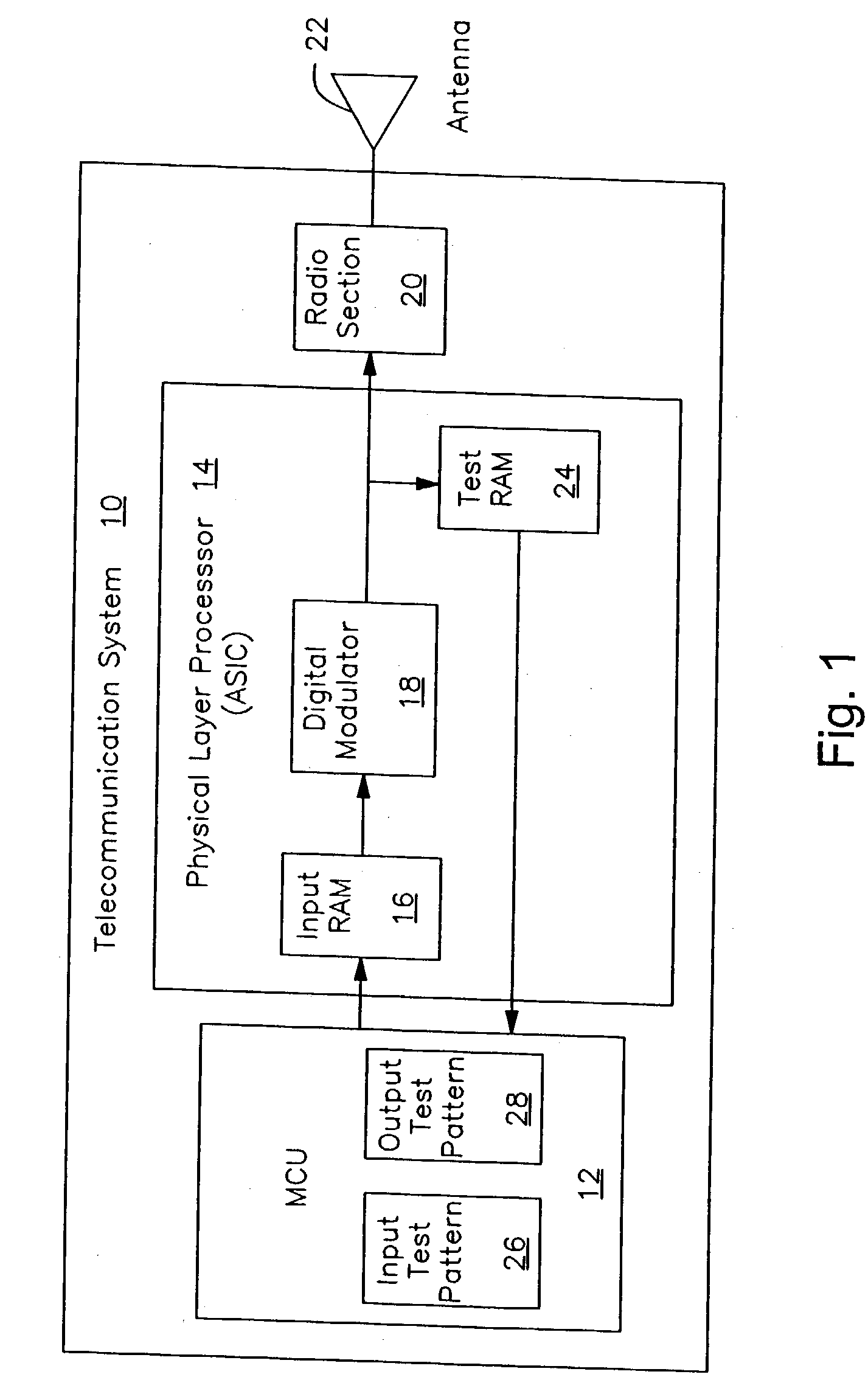
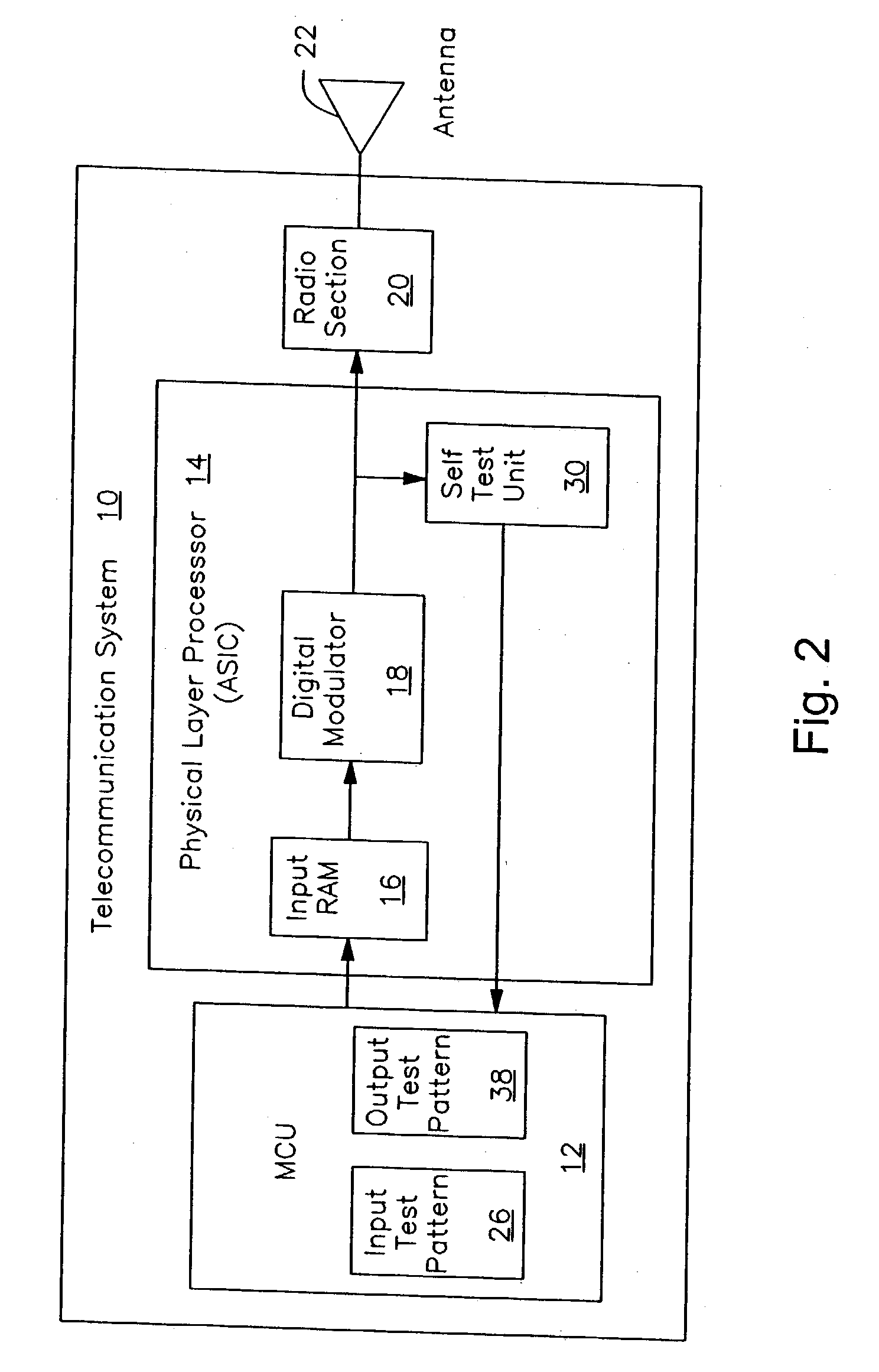
[0033] FIG. 4 shows an alternative configuration for the BIST architecture of the present invention. In FIG. 4, almost all of the BIST functions are contained within the physical layer processor 14, thereby freeing MCU resources for other functions and processes. In FIG. 4, the radio system 10 includes an MCU 12, physical layer processor 14, such as an ASIC and a radio section 20 coupled to an antenna 22. The ASIC includes an input RAM 16 for the bit stream that is to be transmitted and a digital modulator 18 to perform the baseband processing needed for the radio section to send the signal.

[0034] The MCU, in addition to its connection to the input RAM, communicates with the ASIC through a STARTTEST line and a SUCCESS / FAIL flag line. These can be the same or two different lines and can be multiplexed with other control lines if desired. In alternative architectures, the STARTTEST and SUCCESS / FAIL signals can be coupled to some other component of the radio system so that t...


PUM


Abstract

The present invention allows a complex digital processing engine to be tested automatically and autonomously using a minimum of memory and processing resources. In one embodiment, the invention includes an input buffer to store a digital test sequence, a digital data modulator coupled to the input buffer to generate a modulated digital sample sequence using the test sequence, a test buffer coupled to the modulator to receive and store a representation of the sample sequence, and a test buffer output to enable the test buffer contents to be compared to a reference sequence.

Description

[0001] 1. Field[0002] The present invention pertains to the field of built-in self-testing equipment for integrated circuits and in particular to a built-in self-test system for a radio modulator circuit.[0003] 2. Background of the Related Art[0004] Integrated circuit manufacturers have integrated built-in self-test (BIST) directly into very large scale integrated circuit (VLSIC) systems such as microprocessors and memory devices. Such BIST systems have a SELF-TEST pin that can be asserted to cause the VLSIC system to run the integrated self-test and either assert or de-assert a BIST FAIL pin depending on the results.[0005] Digital radio systems present several challenges not present in microprocessors and memory devices. A digital radio system typically includes a digital modulator either as an independent chip set or as part of a larger integrated circuit (IC) device. The modulator receives a particular input data bit stream and upsamples it for transmission. In more detail, it ma...

Claims


Application Information

Patent Timeline
Patent Type & Authority Applications(United States)
IPC IPC(8): G01R31/317H04L1/24
CPCH04L1/242G01R31/31703
Inventor BHORA, VEERENDRABOROS, TIBORROY, PULAKESH
Owner ARRAYCOMM INC
Learn More