
Moving image encoding method, moving image decoding method, and data recording medium

a technology of moving image and decoding method, which is applied in the field of moving pictures, can solve the problem that b-pictures cannot be coded using direct mode under the environment, and achieve the effects of high coding efficiency, reduced number of items, and reduced cos

Inactive Publication Date: 2004-09-30
PANASONIC CORP
View PDF3 Cites 116 Cited by
  • Summary
  • Abstract
  • Description
  • Claims
  • Application Information

AI Technical Summary

Benefits of technology

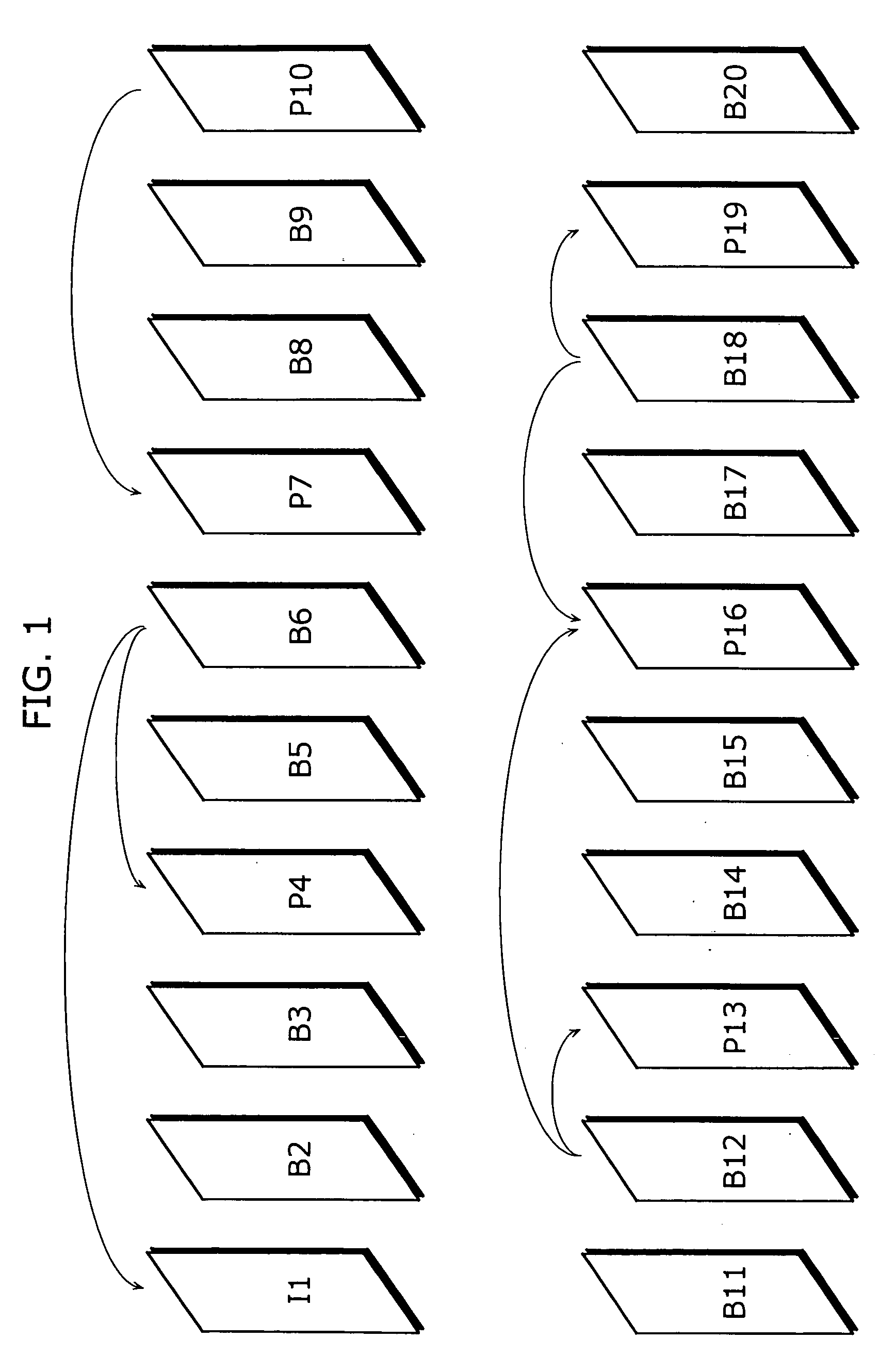
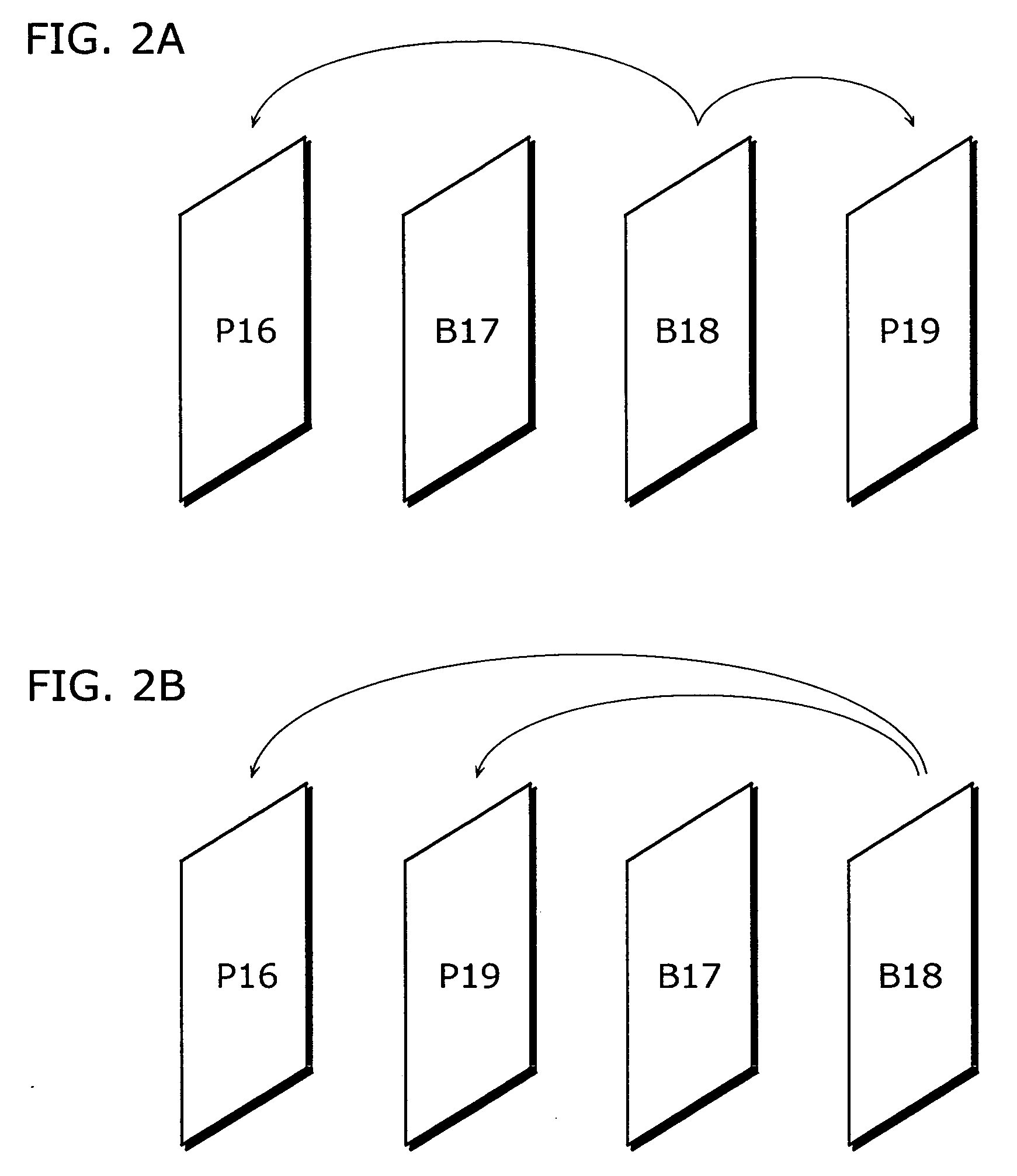
[0022] As described above, the moving picture coding method according to the present invention suggests a method for realizing the direct mode without reference to any temporally subsequent pictures for predictive coding in direct mode even under the environment where temporally subsequent pictures are not available for reference, and further makes it possible to achieve high coding efficiency by reducing the number of items in a table for coding modes by eliminating items on reference to subsequent pictures from the table.
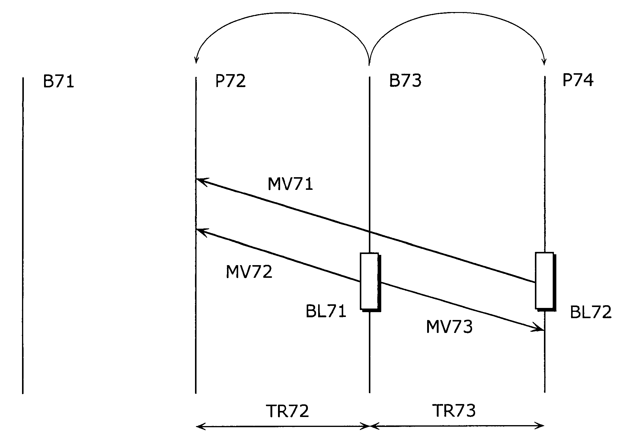
[0120] It should be noted that when coding in direct mode, it is also possible to perform motion compensation in direct mode by considering a value of a motion vector for a current block to be coded as "0" and the immediately preceding picture as a reference picture, instead of performing motion compensation with reference to the blocks located in the positions as shown in FIG. 3A and FIG. 3B. Use of this method makes it unnecessary to execute a step of calculating a motion vector used for the direct mode, and thus simplification of coding processing can be achieved.

Problems solved by technology

Therefore, B-pictures cannot be coded using direct mode under the environment where temporally subsequent pictures cannot be coded and decoded previously.

Method used


Image

  • Moving image encoding method, moving image decoding method, and data recording medium
  • Moving image encoding method, moving image decoding method, and data recording medium
  • Moving image encoding method, moving image decoding method, and data recording medium

Examples


first embodiment

[0050] FIG. 6 is a block diagram showing a structure of a moving picture coding apparatus 100 that executes a moving picture coding method of the The moving picture coding apparatus 100 is a moving picture coding apparatus that determines a motion vector of a current block to be coded with reference to motion vectors of coded blocks around the current block in the same picture when referring only to the pictures that precede the current picture in display order for coding a B-picture in direct mode, and it includes a frame memory 101, a prediction error coding unit 102, a coded stream generation unit 103, a prediction error decoding unit 104, a frame memory 105, a motion vector estimation unit 106, a mode selection unit 107, a motion vector storage unit 108, a subsequent picture judgment unit 109, a difference calculation unit 110, an addition unit 111, a switch 112 and a switch 113. The frame memory 101, the frame memory 105 and the motion vector storage unit 108 are memories real...

second embodiment

[0074] The moving picture decoding method in the second embodiment of the present invention will be explained using a block diagram as shown in FIG. 13. However, it is supposed that the coded stream generated by the moving picture coding method in the first embodiment is decoded by the present moving picture decoding method.

[0075] FIG. 13 is a block diagram showing a structure of a moving picture decoding apparatus 200 in the present embodiment. The moving picture decoding apparatus 200 is a moving picture decoding apparatus that decodes a current block to be decoded which has been coded in direct mode using spatial prediction when a flag indicating a direct mode decoding method is "1", and includes a coded stream analysis unit 201, a prediction error decoding unit 202, a frame memory 203, a motion compensation decoding unit 204, a motion vector storage unit 205, a subsequent picture judgment unit 206, an addition unit 207 and a switch 208.

[0076] The coded stream analysis unit 201 a...

third embodiment

[0096] The moving picture coding method in the third embodiment of the present invention will be explained using a block diagram as shown in FIG. 6.

[0097] A moving picture to be coded is inputted to the frame memory 101 in time order on a picture-by-picture basis. Each picture is divided into blocks called macroblocks of horizontal 16.times.vertical 16 pixels, for example, and the following processing is performed on a block-by-block basis.

[0098] A macroblock read out from the frame memory 101 is inputted to the motion vector estimation unit 106. Here, motion estimation for a current macroblock to be coded is performed using images obtained by decoding coded pictures stored in the frame memory 105. The mode selection unit 107 determines the optimum prediction mode with reference to motion vectors used for the coded pictures and stored in the motion vector storage unit 108. The subsequent picture judgment unit 109 judges whether the subsequent pictures in display order have already b...


PUM


Abstract

A method for realizing a direct mode without reference to temporally subsequent pictures but with reference to motion vectors of coded blocks in one picture including a current block is suggested for performing predictive coding on the current block using the direct mode under the environment where such temporally subsequent pictures are not available for reference, and further, high coding efficiency is achieved even in a case of motion compensation with only forward reference by eliminating items concerning reference to the subsequent pictures from a table of coding modes and thus reducing the number of items in the table.

Description

[0001] The present invention relates to methods for coding and decoding moving pictures, and particularly to a predictive coding method and a predictive decoding method of B-pictures which are predictively coded with reference to a plurality of temporally preceding or subsequent coded pictures.[0002] Generally in moving picture coding, information amount is compressed by suppressing the spatial and temporal redundancies that exist within moving pictures. In inter picture predictive coding as a method of suppressing the temporal redundancies, pictures temporally preceding or subsequent to a current picture are used as reference pictures. Motion estimation and motion compensation are performed per block to generate a predictive picture, and a difference between the predictive picture and the current picture is coded.[0003] In H.26L that is a moving picture coding method which is now being developed for standardization, the following three types of pictures are suggested: I-pictures wh...

Claims


Application Information

Patent Timeline
Patent Type & Authority Applications(United States)
IPC IPC(8): G06T9/00H04N7/26H04N7/32H04N7/36H04N7/46H04N7/50
CPCH04N19/56H04N19/46H04N19/51H04N19/513H04N19/61H04N19/577H04N19/174H04N19/90H04N19/93H04N19/573H04N19/107
Inventor ABE, KIYOFUMIKADONO, SHINYAKONDO, SATOSHIHAGAI, MAKOTO
Owner PANASONIC CORP
Learn More