
Exhaust gas purifying apparatus and method for internal combustion engine, and engine control unit

a technology of exhaust gas purification apparatus and internal combustion engine, which is applied in the direction of machine/engine, exhaust treatment electric control, separation process, etc., can solve the problems of exacerbated degraded nox reduction performance of the nox selective reduction catalyst, and increased exhaust gas characteristics of the engin

Inactive Publication Date: 2004-08-19
HONDA MOTOR CO LTD
View PDF6 Cites 41 Cited by
  • Summary
  • Abstract
  • Description
  • Claims
  • Application Information

AI Technical Summary

Benefits of technology

[0011] According to this exhaust gas purifying apparatus for an internal combustion engine, the NOx detector detects the NOx concentration in the exhaust passage at a location downstream of the NOx selective reduction catalyst, and the supply amount determining means determines the amount of the reducing agent supplied to the NOx selective reduction catalyst such that the NOx concentration detected by the NOx detector reaches an extreme value. When the exhaust gas purifying apparatus employs a reducing agent such as ammonia or the like with which the NOx detector characteristically reacts, if an excessive amount of reducing agent is supplied to the NOx selective reduction catalyst, an increase in ammonia not consumed in the NOx reduction causes a higher concentration of ammonia in exhaust gases in downstream parts of the NOx selective reduction catalyst, so that the NOx sensor, positioned in the exhaust passage at a location downstream of the NOx selective reduction catalyst, detects a value which apparently indicates a high NOx concentration. On the other hand, if an excessively small amount of reducing agent is supplied to the NOx selective reduction catalyst, the NOx selective reduction catalyst suffers from degraded NOx reduction performance, so that the NOx concentration in exhaust gases at a location downstream of the NOx selective reduction catalyst presents a high value, causing the NOx detector to detect a high NOx concentration. For the reason set forth above, the NOx concentration detected by the NOx detector has an extreme value for a particular amount of reducing agent supplied to the NOx selective reduction catalyst. This fact has also been confirmed by experiments. Bearing this in mind, according to the exhaust gas purifying apparatus of the present invention, the supply amount determining means determines the supply amount of the reducing agent such that the NOx concentration detected by the NOx detector reaches the extreme value, so that the supply amount of the reducing agent can be appropriately determined in such a manner that both the ammonia concentration and NOx concentration in exhaust gases at a location downstream of the NOx selective reduction catalyst present low values in a well balanced state. As a result, high NOx purification performance can be ensured to securely provide good exhaust gas characteristics.
[0034] This preferred embodiment of the engine control unit provides the same advantageous effects as provided by the corresponding preferred embodiment of the exhaust gas purifying apparatus.

Problems solved by technology

As a result, the amount of ammonia supplied to the NOx selective reduction catalyst is not appropriately determined in accordance with the actual purification of NOx by the NOx selective reduction catalyst, possibly exacerbating the exhaust gas characteristics of the engine.
As a result, since the NOx sensor fails to correctly detect the NOx concentration in exhaust gases, the ECU does not determine an appropriate amount of ammonia supplied to the NOx selective reduction catalyst, possibly resulting in exacerbated exhaust gas characteristics of the engine.
On the other hand, if an excessively small amount of reducing agent is supplied to the NOx selective reduction catalyst, the NOx selective reduction catalyst suffers from degraded NOx reduction performance, so that the NOx concentration in exhaust gases at a location downstream of the NOx selective reduction catalyst presents a high value, causing the NOx detector to detect a high NOx concentration.

Method used


Image

  • Exhaust gas purifying apparatus and method for internal combustion engine, and engine control unit
  • Exhaust gas purifying apparatus and method for internal combustion engine, and engine control unit
  • Exhaust gas purifying apparatus and method for internal combustion engine, and engine control unit

Examples


Embodiment Construction

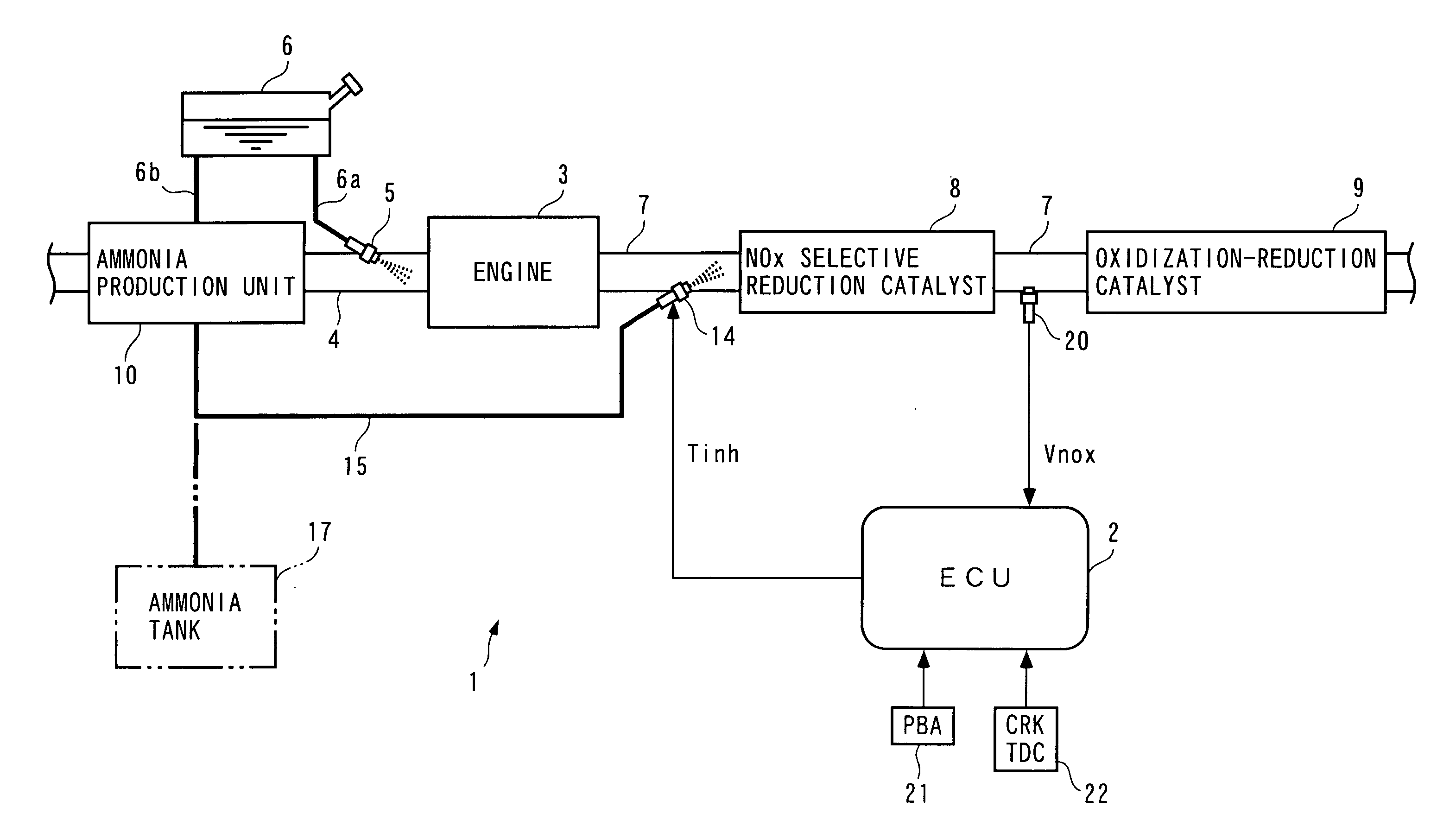
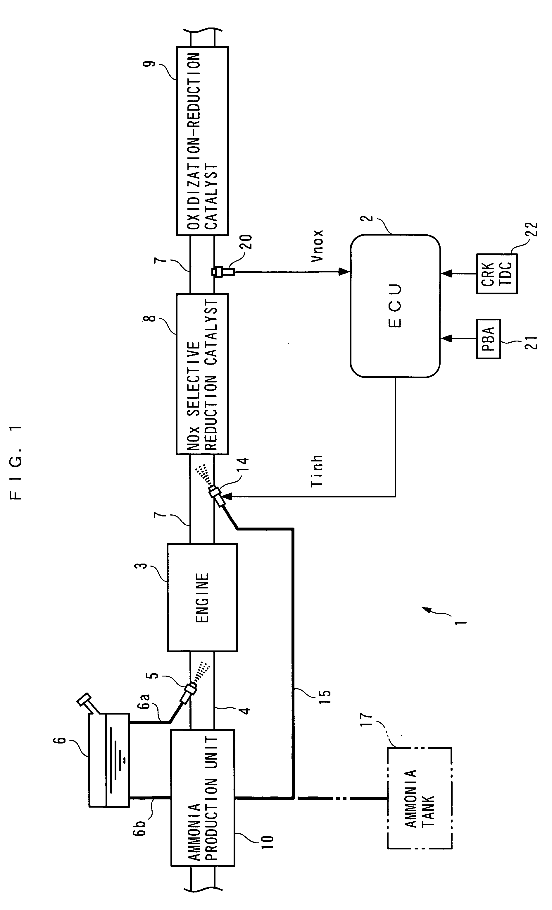
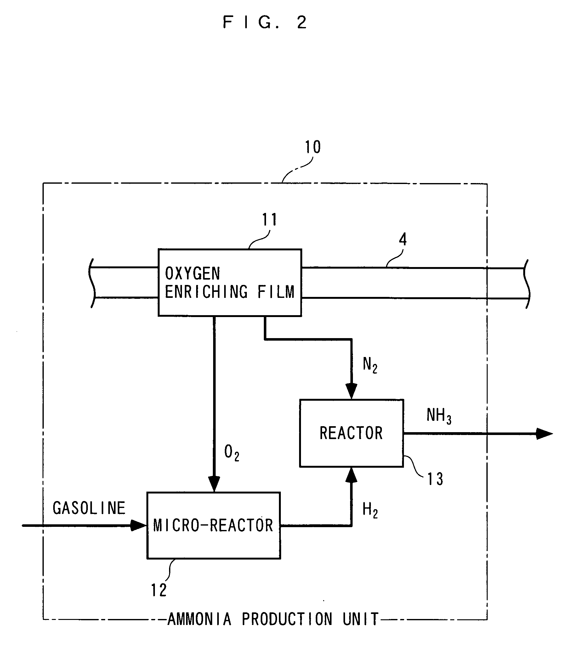
[0049] In the following, an exhaust gas purifying apparatus for an internal combustion engine according to a first embodiment of the present invention will be described with reference to the accompanying drawings. FIG. 1 generally illustrates the configuration of an exhaust gas purifying apparatus 1 according to the first embodiment, and an internal combustion engine (hereinafter called the "engine") 3 which applies the exhaust gas purifying apparatus 1. As illustrated, the exhaust gas purifying apparatus 1 comprises an ECU 2; an ammonia production unit 10 for producing ammonia; an injector 14 for injecting ammonia; and the like. The ECU 2 controls the amount of ammonia (NH.sub.3) injected by the injector 14, as later described.

[0050] The engine 3 is a gasoline engine of lean burn operation type, and is equipped in a vehicle, not shown. An injector 5 is provided halfway in an intake pipe 4 of the engine 3 for injecting a fuel. The injector 5 is connected to a fuel tank 6 through a f...


PUM


Abstract

An exhaust gas purifying apparatus and method for an internal combustion engine, and an engine control unit are provided for appropriately determining the amount of reducing agent supplied to a NOx selective reduction catalyst to ensure good exhaust gas characteristics. The exhaust gas purifying apparatus comprises an ECU; a NOx selective reduction catalyst for purifying NOx in exhaust gases in an exhaust pipe; a NOx sensor disposed in the exhaust pipe at a location downstream of the NOx selective reduction catalyst for detecting a NOx concentration in exhaust gases; and an injector for supplying the NOx selective reduction catalyst with ammonia produced in an ammonia production unit. The ECU determines the amount of ammonia injected to the NOx selective reduction catalyst by the injector such that an estimate of the NOx concentration detected by the NOx sensor reaches a minimum value.

Description

[0001] 1. Field of the Invention[0002] The present invention relates to an exhaust gas purifying apparatus and method for an internal combustion engine, and an engine control unit for purifying nitrogen oxides (NOx) within exhaust gases which flow through an exhaust passage by a NOx selective reduction catalyst under the existence of a reducing agent.[0003] 2. Description of the Prior Art[0004] The type of conventional exhaust gas purifying apparatus for an internal combustion engine mentioned above is known, for example, from Japanese Patent Publication No. 6-35816. This exhaust gas purifying apparatus injects ammonia as a reducing agent to a NOx selective reduction catalyst from an upstream location of an exhaust passage. This exhaust gas purifying apparatus, which is applied to a diesel engine equipped in a vehicle, comprises an ammonia production unit for producing ammonia; an ammonia supply unit for supplying produced ammonia to a location in the exhaust passage upstream of the...

Claims


Application Information

Patent Timeline
IPC IPC(8): B01D53/94F01N3/08F01N3/24F01N3/20F01N3/28F01N9/00F01N13/02
CPCF01N3/2066F01N3/36F01N9/00F01N2240/25F01N2240/30F01N13/009F01N2610/02F01N2610/14F01N2610/146Y02T10/47Y02T10/24F01N2560/026Y02T10/12Y02T10/40
Inventor YASUI, YUJIIWAMOTO, JUNOGIHARA, HIDEMI
Owner HONDA MOTOR CO LTD
Learn More