Information storage systems
a technology of information storage and information storage, applied in the direction of magnetic recording, magnetic material for record carriers, recording/reproducing/erasing methods, etc., can solve the problems of head crash, significant damage to the surface of the platter, and the potential fragility of conventional hard disk drives, so as to achieve greater flexibility of use and improve performan
- Summary
- Abstract
- Description
- Claims
- Application Information
AI Technical Summary
Benefits of technology
Problems solved by technology
Method used
Image

Examples
first embodiment
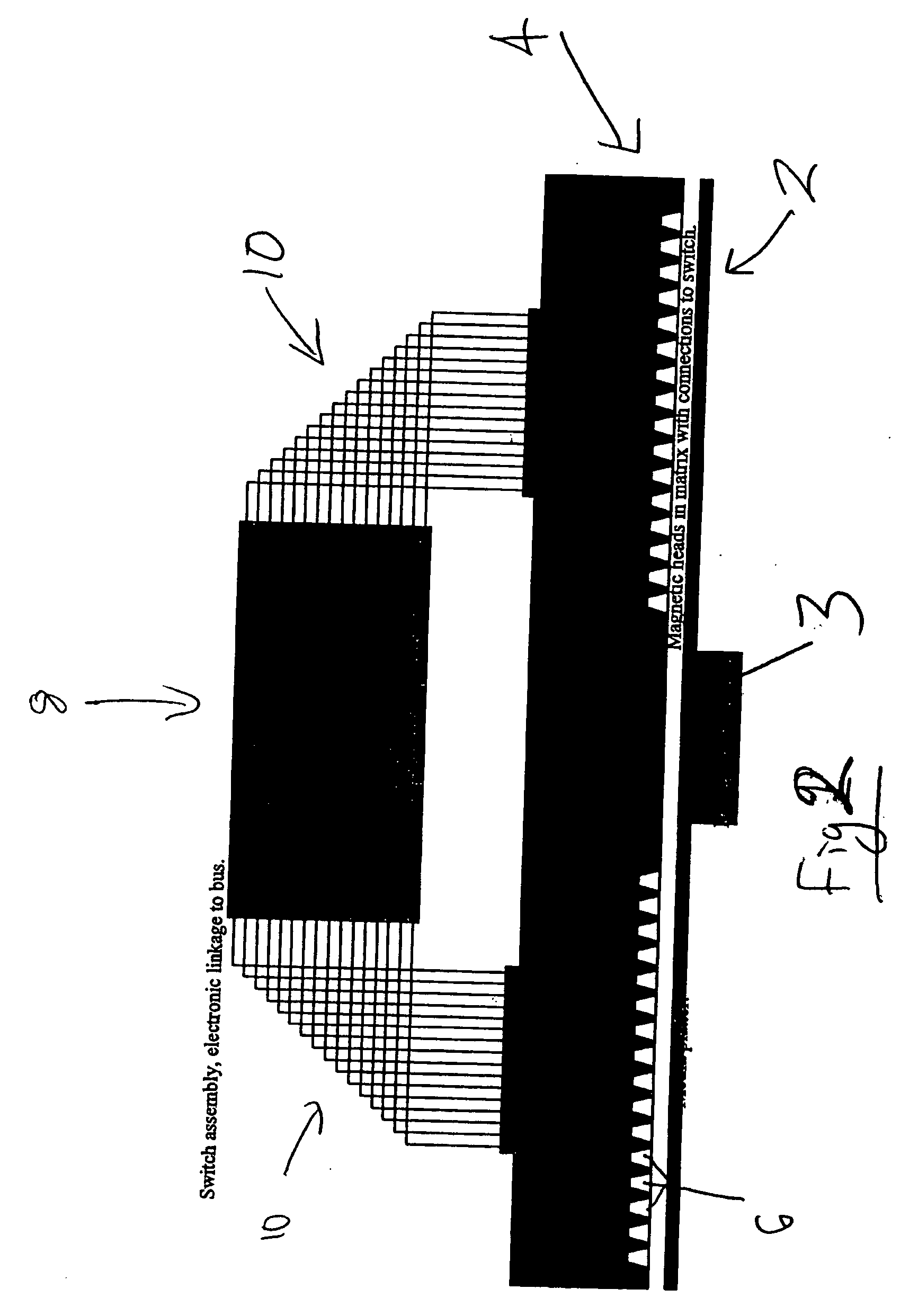
[0159] Similarly, the head assembly 32 is fabricated as described above and is covered with an artificial diamond layer 34. However, in this embodiment, the shape of the two members is such that the data tracks 14' are not arranged in circles or spirals but rather in parallel rows. By analogy with the circular embodiment the heads 6' in adjacent rows are mutually offset so as to enable optimum packing of the heads. The arrangement of heads 6' relative to the data tracks 14' may be seen in FIG. 10a. Another difference as compared with the first embodiment is that it is not necessary to provide holes through the ceramic substrate of the head array to make electrical connections to the heads since these may be made at either side of the head sliding member 22.
[0160] Considering FIGS. 11a to 11c, these show respectively schematic plan and side sectional views and an end view of the information storage device. The magnetic data storage member 20 is mounted so as to be able to slide in tw...
example 1
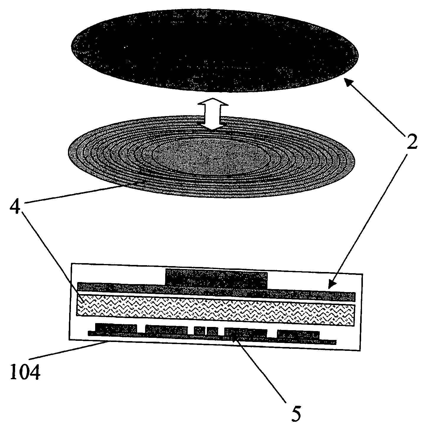
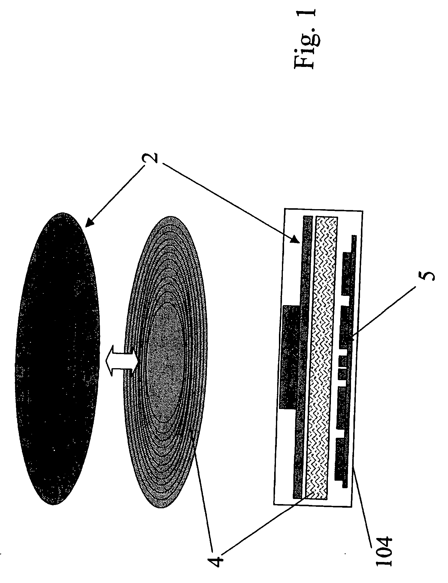
[0167] A particular practical example of the circular embodiment described above is now given. The usable band of magnetic material on the information storage disk 4 has an inner diameter of approximately 40 mm and an outer diameter of approximately 120 mm. The read / write heads on the corresponding head array disk are therefore arranged in spirals extending in a single revolution from an inner to an outer diameter which diameters correspond to the dimensions of the band of magnetic medium.
[0168] The length L of a single revolution spiral extending from the inside diameter to the outside diameter of a circular disk is given by the formula:
L=.pi.(D.sub.i+D.sub.o) / 2
[0169] where
[0170] D.sub.i=inner diameter
[0171] D.sub.o=outer diameter
[0172] For a disk with an inner diameter of approximately 40 mm and an outer diameter of approximately 120 mm the length of each spiral track is therefore approximately 250 mm.
[0173] The size and shape of the heads and the pitch of the spirals are such as ...
example 2
[0180] A particular example of the rectangular embodiment described above will now be given. In this example the length of the area of the magnetic medium 28 is 165 mm and the width is 25 mm.
[0181] As in Example 1 the size and shape of the heads and the pitch of the mutual offset between adjacent rows are such as to allow a lateral spacing of the heads of approximately 2.5 microns and a longitudinal spacing between the heads on adjacent rows of approximately 820 microns. This therefore allows for 10,000 heads per row and 200 rows--i.e. a theoretical 2 million heads in total.
[0182] The number of heads in each row corresponds to the number of parallel linear tracks, and there are therefore 10,000 data tracks extending the length of the data member. With a data storage density of 25 bits per linear micron as in the circular embodiment of Example 1, there are a total of 25.times.150.times.100=3.75 million bits. Thus if the maximum number of rows were employed each head would cover appro...
PUM
| Property | Measurement | Unit |
|---|---|---|
| width | aaaaa | aaaaa |
| width | aaaaa | aaaaa |
| width | aaaaa | aaaaa |
Abstract
Description
Claims
Application Information
 - R&D
- Intellectual Property
- Life Sciences
- Materials
- Tech Scout
- Unparalleled Data Quality
- Higher Quality Content
- 60% Fewer Hallucinations
Browse by: Latest US Patents, China's latest patents, Technical Efficacy Thesaurus, Application Domain, Technology Topic, Popular Technical Reports.
© 2025 PatSnap. All rights reserved.Legal|Privacy policy|Modern Slavery Act Transparency Statement|Sitemap|About US| Contact US: help@patsnap.com