Cutting insert including a bracing layer

a cutting insert and bracing technology, applied in the direction of turning tools, milling equipment, turning apparatus, etc., can solve the problems of high cost, increased thickness, and increased risk of chipping or nicking,

Inactive Publication Date: 2004-06-10
SAFETY PROD
View PDF10 Cites 20 Cited by
  • Summary
  • Abstract
  • Description
  • Claims
  • Application Information

AI Technical Summary

Problems solved by technology

However, this thickness must not increased too much as the insert would be unusable for tapping holes of a limited diameter, owing to the contact between the heel of the tooth and the edge of the orifice machined.
It would be conceivable to increase the relief angle, i.e. to reduce the wedge angle of the lateral profile of the cutting edge, but the latter would ...

Method used


Image

  • Cutting insert including a bracing layer
  • Cutting insert including a bracing layer
  • Cutting insert including a bracing layer

Examples


Embodiment Construction

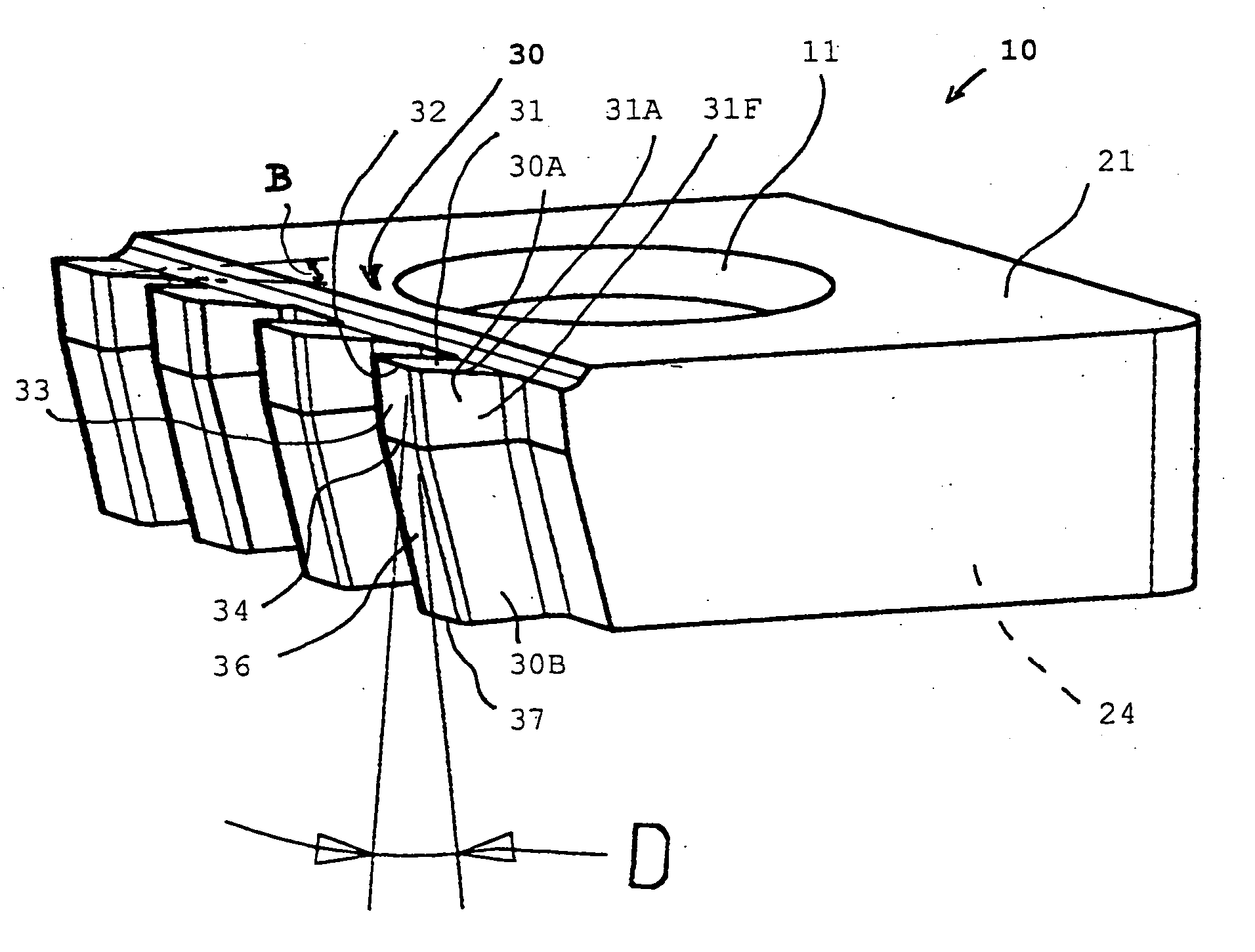
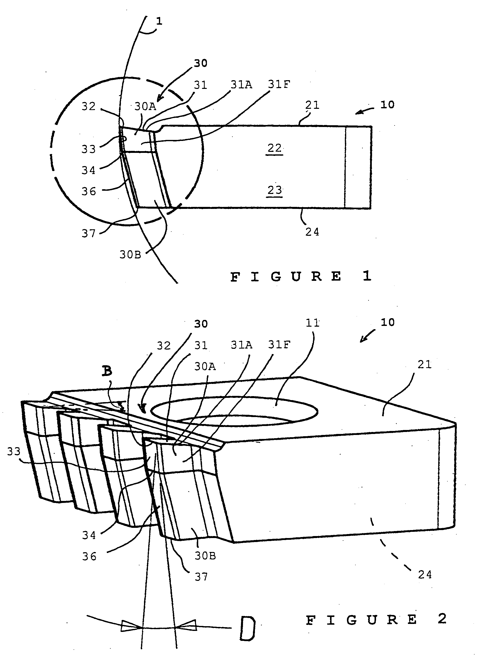
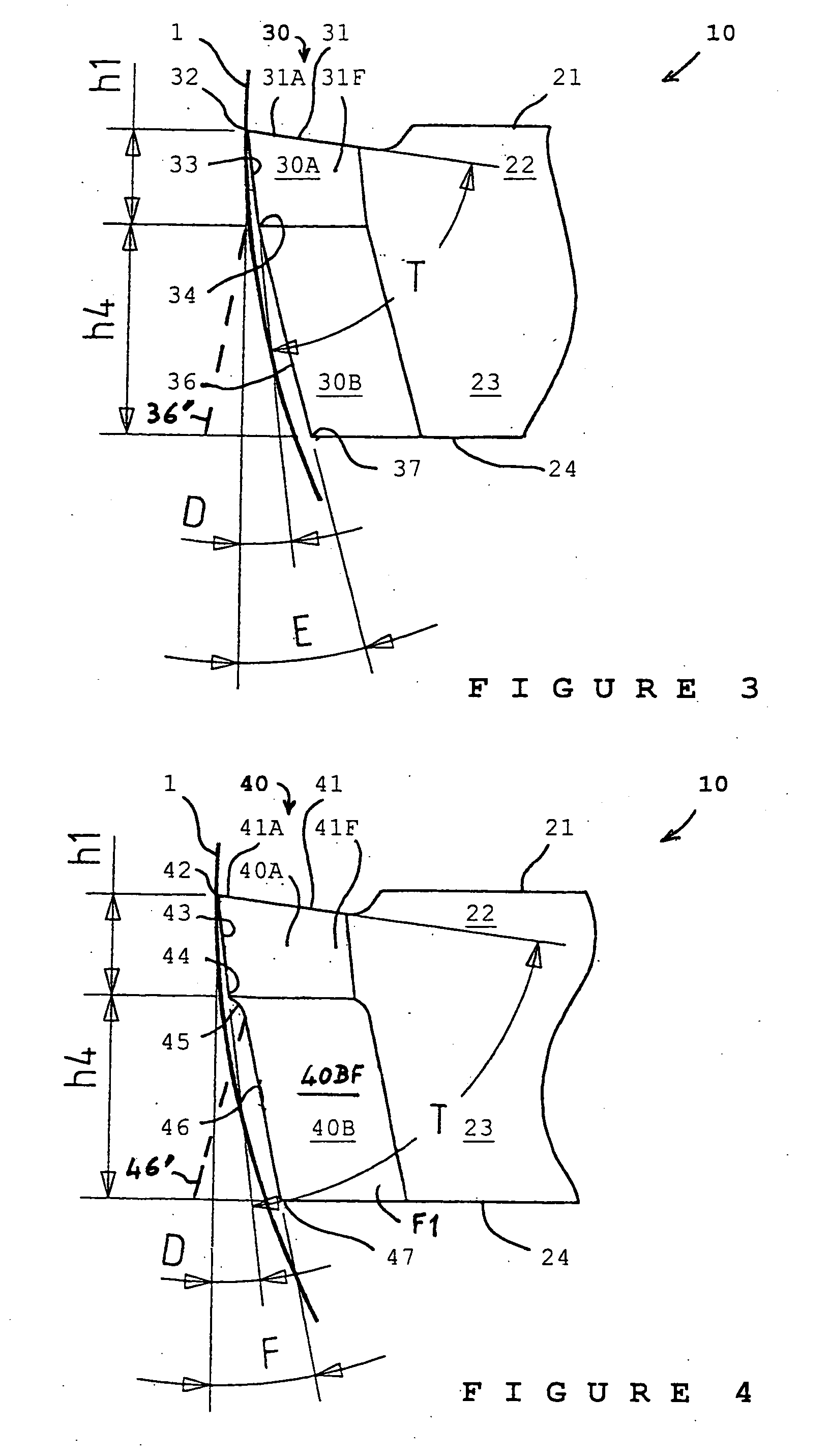
[0037] FIGS. 1, 3 and 2 show, respectively, in cross-section and in perspective, an insert 10 in position for tapping a circular orifice 1 of a work-piece. Insert 10 is pierced here by a hole 11, here vertical, for receiving a screw for removable attachment to a tool holder, not shown.

[0038] Insert 10 has here substantially the shape of a rectangular parallelepiped, with a front face or surface 21 and a back face or surface 24. For the sake of simplicity, faces 21 and 24 are supposed here to be horizontal. One of four lateral, horizontally extending teeth seen in FIG. 2 bears reference number 30 in FIGS. 1 to 3. Tooth 30 has a determined cutting height represented by its lateral extension, projecting from a virtual reference plane, substantially vertical in the figures, tangent to the valleys separating the teeth. Tooth 30 comprises a front face, or cutting face, 31 forming part of front face 21, but which has been ground so as to hollow it out slightly obliquely towards the centre ...


PUM

PropertyMeasurementUnit
Fractionaaaaaaaaaa
Fractionaaaaaaaaaa
Currentaaaaaaaaaa

Abstract

1. The thread cutting insert (10) includes a laterally projecting tooth (30) comprising a front, chip cutting and repelling face (31), delimited by a cutting edge (31A) separating it from a flank area with a profile (33) having a determined overall relief angle (D), characterised by the fact that the tooth comprises, rearwards of a forward volume part (30A) directly supporting the cutting edge (31A) and limited by the flank area extending over a limited thickness (h1), a part (30B) for bracing the forward volume part (30A), having a profile (36) with an average relief angle differing from the overall relief angle (D) of the profile (33) of the flank area.

Description

[0001] The present invention relates to cutting inserts intended for cutting threads, whether internal or external.DESCRIPTION OF RELATED ART[0002] Such a cutting insert has a frontal face moving substantially perpendicularly to the surface to be cut, in order to rake it, with, in addition, an axial feed translation motion, with one or more laterally extending teeth forming a sort of groove-cutting rake. The chips are cut by a cutting edge with a generally V or U-shaped front profile delimiting a ground front face of the tooth against which the chips slide. The cutting edge is bordered by the flanks of the tooth which conventionally have, over the entire thickness of the insert, a controlled surface finish quality, obtained by careful grinding or casting, with a determined relief angle, whether positive or negative, to avoid any unwanted rubbing of the heel, rearwards of the tooth, on the internal or external thread, respectively.[0003] The insert, which is fixed by a central screw ...

Claims


Application Information

Patent Timeline
IPC IPC(8): B23B27/06
CPCB23B27/065B23B27/141Y10T407/23B23B2200/205B23B2200/125
Inventor FOUQUER, RICHARD
Owner SAFETY PROD
Why Eureka
Try Eureka